Electronic product assembly line workbench capable of achieving transverse moving

A technology for electronic products and workbenches, applied in assembly machines, manufacturing tools, metal processing equipment, etc., can solve the problems of inability to meet the requirements of modern assembly, low work efficiency of workers, and inhumane assembly, and achieve simple and convenient structure. Promotion and application, the effect of reducing friction

Inactive Publication Date: 2016-06-08
SHAANXI ZIZHU ELECTRON
View PDF0 Cites 0 Cited by
  • Summary
  • Abstract
  • Description
  • Claims
  • Application Information

AI Technical Summary

Problems solved by technology

[0002] In the current electronic assembly line, since the manufacture of some parts involves many processes, the corresponding processes will be assembled at different stations, and these assembly stations are still set discontinuously. In order to ensure these different The requirements for the assembly line operation of standard parts require that the parts of these assembly stations need to be transferred to other assembly stations, so that they need to be transferred to another station through traversing equipment. At present, most of the existing assembly lines cannot be traversing The workbench is very inconvenient to operate when assembling parts of different sizes, and sometimes it needs to use certain tools to complete, which results in low work efficiency for workers, unhuman assembly, and cannot meet the requirements of modern assembly

Method used


Image

  • Electronic product assembly line workbench capable of achieving transverse moving
  • Electronic product assembly line workbench capable of achieving transverse moving

Examples


Embodiment Construction

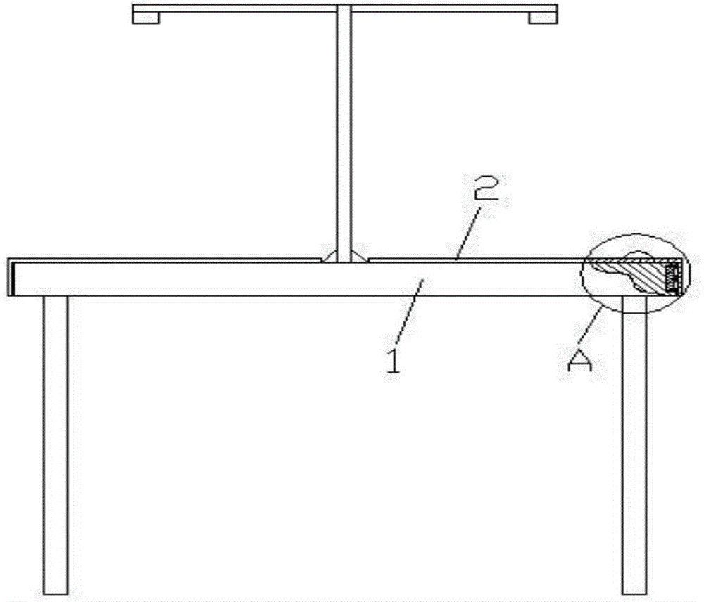
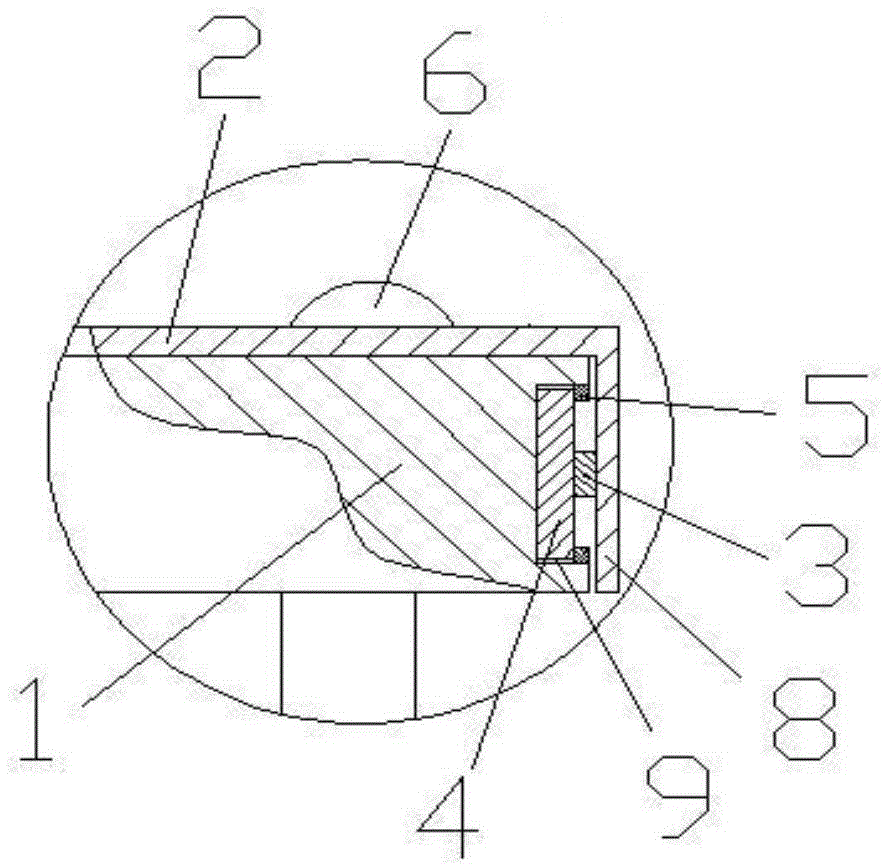
[0019] like figure 1 , figure 2 The shown workbench of a transversally movable electronic product assembly line includes a workbench 1, which is characterized in that: the upper part of the side surface of the workbench 1 close to the staff is provided with a U-shaped groove 9, and the U-shaped groove Two rollers 4 are arranged in parallel in the groove 9, and a cover plate is arranged on the workbench 1, and the cover plate includes a horizontal cover plate 2 installed on the upper surface of the workbench 1 and a vertical roller vertically connected with the horizontal cover plate 2. Cover plate 8, the vertical cover plate 8 is covered above the U-shaped groove 9, the inner side of the vertical cover plate 8 is connected with the roller 4 through the rotating shaft 3, and the distance between the two rollers 4 is less than that of the roller 4. Three times the diameter of the cross-section, the upper and lower sides of the U-shaped groove 9 are respectively provided with r...


PUM


Abstract

The invention discloses an electronic product assembly line workbench capable of achieving transverse moving. The workbench comprises a workbench body, a U-shaped groove is formed in the upper portion of the side surface of the workbench body, and two rolling wheels are arranged in the U-shaped groove in parallel. A cover plate is arranged on the workbench body and comprises a horizontal cover plate body installed on the upper surface of the workbench body and a vertical cover plate body perpendicularly connected with the horizontal cover plate body. The inner side of the vertical cover plate body is connected with the rolling wheels through a rotary shaft. Barrier strips used for preventing the rolling wheels from falling out of the U-shaped groove are arranged on the upper and lower sides of the inside of the U-shaped groove. A handle used for pushing the horizontal cover plate body to move transversely is installed on the horizontal cover plate body. According to the workbench, the horizontal cover plate body moves transversely so as to drive the vertical cover plate body connected with the horizontal cover plate body to move, and then the vertical cover plate body drives the rolling wheels to roll in the U-shaped groove; friction force is reduced so that the horizontal cover plate body can smoothly move transversely, parts are conveyed transversely, convenience is brought to assembly, the working efficiency of workers is improved, and the requirement for assembly modernization is met.

Description

technical field [0001] The invention belongs to the technical field of electronic product assembly equipment, and in particular relates to a transversely movable workbench of an electronic product assembly line. Background technique [0002] At present, in the existing electronic assembly line, because the manufacture of certain parts involves many processes, the corresponding processes will be assembled in different stations, and these assembly stations are still set discontinuously. In order to ensure these different The requirements for the assembly line operation of standard parts require that the parts of these assembly stations need to be transferred to other assembly stations, so that they need to be transferred to another station through traversing equipment. At present, most of the existing assembly lines cannot be traversing The workbench is very inconvenient to operate when assembling parts of different sizes, and sometimes it needs to use certain tools to complet...

Claims


Application Information

Patent Timeline
Patent Type & Authority Applications(China)
IPC IPC(8): B23P21/00
Inventor 董焕萍田伟国孙骏
Owner SHAANXI ZIZHU ELECTRON
Why Eureka
Try Eureka