A patch head of a placement machine

A chip mounter and chip mounter technology, which is applied in the direction of assembling printed circuits with electrical components, can solve the problems of not being able to guarantee the consistency and stability of the amplitude change, and achieve the effect of simple structure and guaranteed consistency

Active Publication Date: 2019-01-04
深圳市森阳智能制造装备有限公司
View PDF9 Cites 0 Cited by
  • Summary
  • Abstract
  • Description
  • Claims
  • Application Information

AI Technical Summary

Problems solved by technology

Although the invention installs all the placement heads on the placement head mounting seat respectively, and adjusts the position by installing the backboard assembly and the placement head suction nozzle assembly respectively through the placement head, so that the placement head can realize the variable amplitude movement, which is beneficial to improving the performance of the overall placement machine The performance has a very good effect, but its horizontal luffing movement mode and the installation of the backplane assembly make the patch head of this invention patent unable to guarantee the consistency and stability of the luffing

Method used


Image

  • A patch head of a placement machine
  • A patch head of a placement machine
  • A patch head of a placement machine

Examples


Embodiment Construction

[0038] The present invention will be further described in detail below with reference to the drawings and specific embodiments.

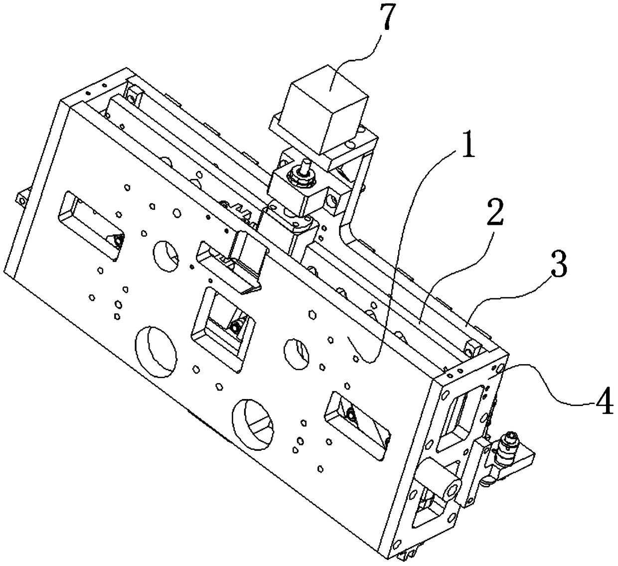
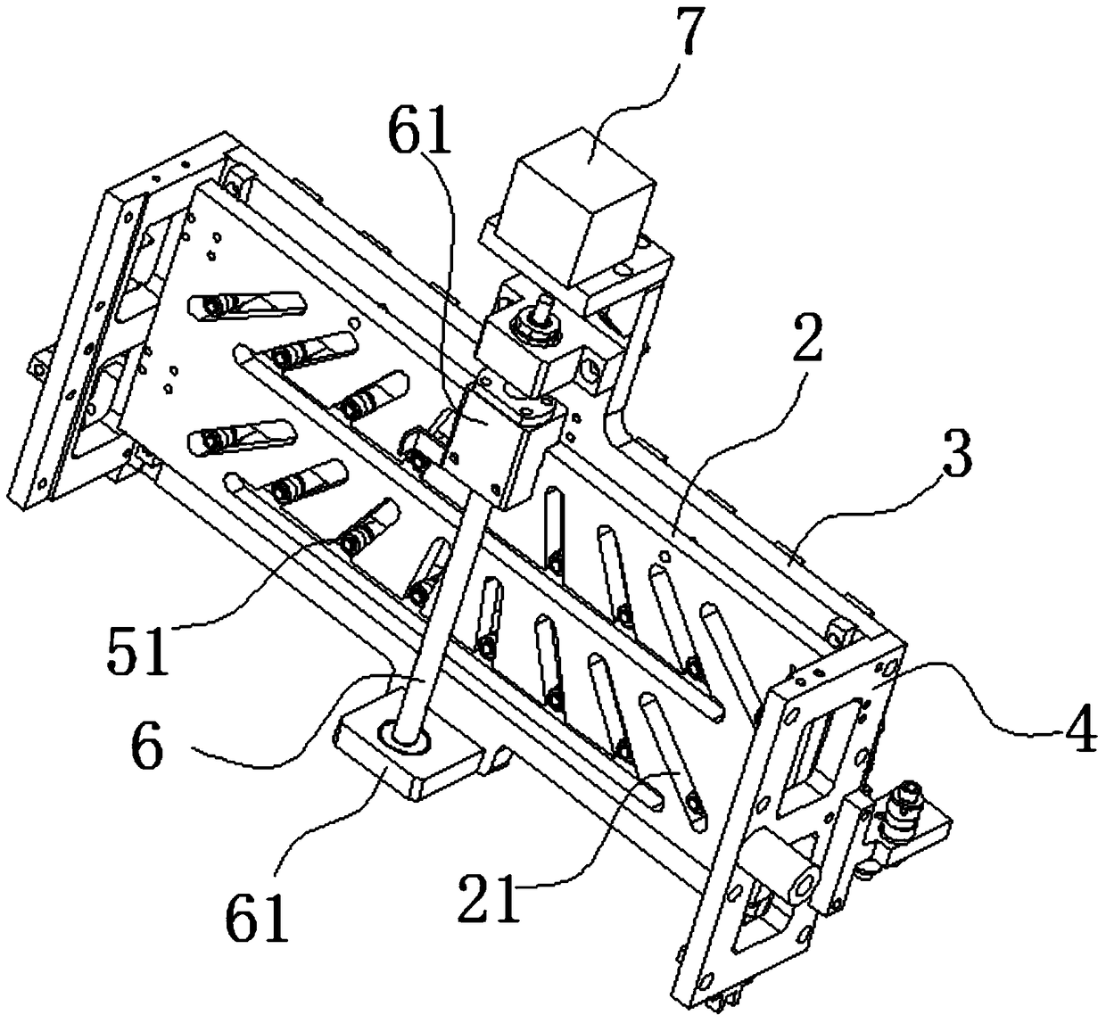
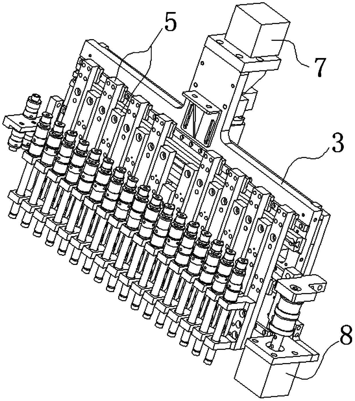
[0039] See Figure 1 to Figure 4 As shown, the placement head of the placement machine includes a mounting assembly and a plurality of nozzle assemblies 5, and the plurality of nozzle assemblies 5 are installed side by side on the mounting assembly laterally. Among them, the mounting assembly includes a guide plate 2 and a mounting plate 3.

[0040] The guide plate 2 and the mounting plate 3 are arranged in layers. The guide plate 2 is provided with a plurality of guide holes 21, the guide holes 21 include the inner wall of the holes, and the guide holes 21 are arranged obliquely.

[0041] Furthermore, the guide plate 2 has an axisymmetric structure in the lateral direction, and the plurality of guide holes 21 on the guide plate 2 are arranged obliquely, and the plurality of obliquely arranged guide holes 21 are distributed axisymmetrically about the symm...


PUM


Abstract

The invention provides a chip mounting head of a chip mounting machine. The chip mounting head comprises a mounting component and a plurality of suction nozzle components, wherein the suction nozzle components are transversely parallelly mounted on the mounting component; the mounting component comprises a guide plate and a mounting plate which are arranged in a layered manner; the guide plate is provided with a plurality oblique guide holes; each guide hole comprises an inner wall, and a guide column can be inserted into the guide hole; each suction nozzle component comprises the guide column and a suction nozzle support which are integrally connected; the mounting plate is movably connected with the suction nozzle supports and provided with a movable guide rail, and the suction nozzle supports can transversely move along the movable guide rail; the guide columns move along the hole inner walls to allow the suction nozzle supports to transversely move along the movable guide rail. The chip mounting head has the advantages that the chip mounting head is stable in operation, and overall consistency of suction nozzle supports after transverse adjustment is guaranteed.

Description

Technical field [0001] The invention relates to a placement machine, in particular to a component picking and pasting mechanism of the placement machine. Background technique [0002] With the continuous development of the electronics industry, chip placement operations are mostly performed on PCB boards. In order to perform placement work efficiently and accurately, placement machines have emerged during the continuous development of the industry. The emergence of the placement machine has solved the problem of slow manual production and difficulty in accurate placement. [0003] The placement machine is a device that accurately places surface-mounted components on the PCB pads by moving the placement head, including manual and fully automatic types. Among them, the automatic placement machine is used to realize high-speed, high-precision and automatic placement of components, and it is the most critical and complex equipment in the entire SMT (Surface Mounted Technology) product...

Claims


Application Information

Patent Timeline
Patent Type & Authority Patents(China)
IPC IPC(8): H05K3/30
Inventor 张垒张艳
Owner 深圳市森阳智能制造装备有限公司
Why Eureka
Try Eureka