An adjustable-length stamping protection device

A technology of protective layer and front side plate, which is applied in the field of stamping protection device, can solve the problems of position interference, inconvenient use, non-adjustable length of stamping protection device, etc., and achieve the effect of high production efficiency and convenient use

Inactive Publication Date: 2017-10-03
CHONGQING BEIHUA TECH
View PDF5 Cites 0 Cited by
  • Summary
  • Abstract
  • Description
  • Claims
  • Application Information

AI Technical Summary

Problems solved by technology

[0003] In view of the above-mentioned shortcomings of the prior art, the purpose of the present invention is to provide a length-adjustable stamping protection device, which is used to solve the problem that the length of the stamping protection device in the prior art is not adjustable, it is easy to cause position interference, and it is not easy to use. Convenience and other issues

Method used


Image

  • An adjustable-length stamping protection device
  • An adjustable-length stamping protection device
  • An adjustable-length stamping protection device

Examples


Embodiment Construction

[0045] The implementation of the present invention will be illustrated by specific specific examples below, and those skilled in the art can easily understand other advantages and effects of the present invention from the contents disclosed in this specification.

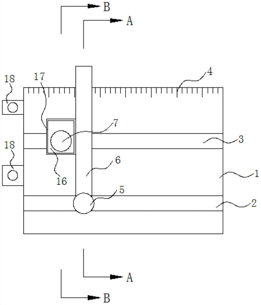
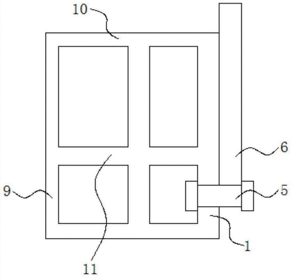
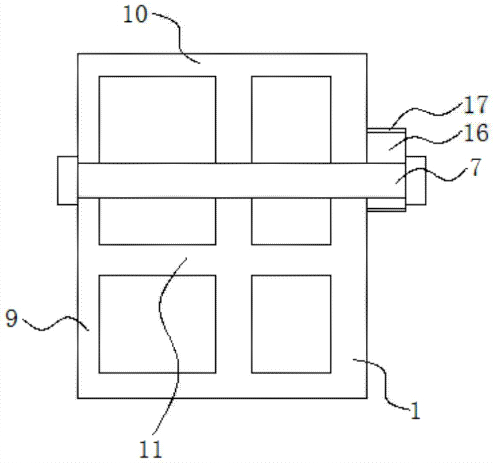
[0046] see Figure 1 to Figure 8 . It should be noted that the structures, proportions, sizes, etc. shown in the drawings attached to this specification are only used to match the content disclosed in the specification, for those who are familiar with this technology to understand and read, and are not used to limit the implementation of the present invention. Limiting conditions, so there is no technical substantive meaning, any modification of structure, change of proportional relationship or adjustment of size, without affecting the effect and purpose of the present invention, should still fall within the scope of the present invention. The disclosed technical content must be within the scope covered. At the sa...


PUM


Abstract

The invention provides a punching position protection device with an adjustable length. The punching position protection device comprises multiple front side plates and rear side plates; baffle plates are arranged on the front side plates; the upper parts of the front side plates and the rear side plates are connected with upper flat plates; each front side plate is provided with a first sliding groove and a second sliding groove; each rear side plate is provided with a third sliding groove; a movable pin is arranged on each first sliding groove; a locking component is arranged on each second sliding groove in a penetration manner, and a locking component is arranged on each third sliding groove in a penetration manner; the outer side of each front side plate is detachably connected with a magnetic component which can attract and close the corresponding baffle plate through the corresponding locking component; the lower end of each baffle plate is hinged to the corresponding movable pin; the upper end of each baffle plate extends out of the upper surface of the corresponding upper flat plate; one end of each rear side plate is provided with connection plates, and the other end of each rear side plate is provided with connection holes; each connection plate extends out of the end part of the corresponding rear side plate; the inner wall of each front side plate is provided with support lugs; the connection plates and the corresponding lugs are all provided with screw holes; and a bolt is arranged in each connection hole and the screw holes in the corresponding connection plate and support lug. According to the punching position protection device, the length can be flexibly adjusted; assembly and maintenance are convenient; the production cost is low; and the production efficiency is high.

Description

technical field [0001] The invention belongs to the field of mechanical processing equipment, and in particular relates to a length-adjustable stamping protection device. Background technique [0002] Plate-shaped metal materials usually need to be punched in a punching machine, and the position of the punching hole must be accurate enough. Due to the large surface area of ​​the metal plate, a protective device is usually required to protect the punching plate during punching, so that the punching machine can punch. The exact position of the plate is punched. However, the size of the stamping plate is large, and the requirements for the position of the punching hole are different. The existing position protection device is poor in flexibility, and it is difficult to adapt to the punching of the stamping plate of different sizes and different punching position requirements. Hole processing, the baffle is easy to cause positional interference to the placement and removal of th...

Claims


Application Information

Patent Timeline
Patent Type & Authority Patents(China)
IPC IPC(8): B21D43/00B21D28/26
CPCB21D28/265B21D43/003
Inventor 陈久江
Owner CHONGQING BEIHUA TECH
Why Eureka
Try Eureka