
Composite sealing cover structure of sulfide-contained mine solid waste landfill field

A solid waste and sulfide technology, applied in the field of environmental geotechnical engineering, can solve the problems of reduced oxygen penetration barrier effect, high later maintenance costs, and difficulty in long-term sustainability, and achieves the effect of eliminating maintenance costs, simple construction and low cost.

Active Publication Date: 2016-06-08
LIAONING TECHNICAL UNIVERSITY
View PDF9 Cites 4 Cited by
  • Summary
  • Abstract
  • Description
  • Claims
  • Application Information

AI Technical Summary

Problems solved by technology

However, similar to the method of adding alkaline substances such as lime, this method also has the problem of being difficult to sustain for a long time
When the organic matter contained in the capping material is consumed, the barrier effect on oxygen permeation will be greatly reduced, and high post-maintenance costs are still required

Method used


Image

  • Composite sealing cover structure of sulfide-contained mine solid waste landfill field
  • Composite sealing cover structure of sulfide-contained mine solid waste landfill field
  • Composite sealing cover structure of sulfide-contained mine solid waste landfill field

Examples


Embodiment 1

[0033] The average annual precipitation in the area where a certain tailings pond is located is 980mm, the wet season is from June to August, and the dry season is from September to March of the next year. The composite cover of the present invention is laid on the surface of the original tailings 4 in the reservoir area.

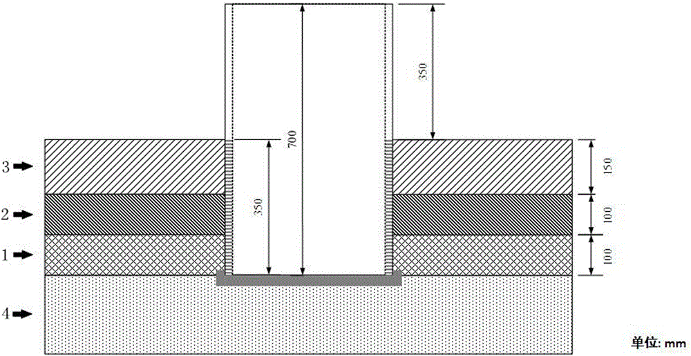
[0034] The composite cover structure of this embodiment is from bottom to top, such as figure 1 As shown, it consists of the first sublayer 1, the second sublayer 2 and the third sublayer 3 in sequence;

[0035] Wherein the first sublayer 1 is directly laid on the surface of the original tailings 4, with a thickness of 10 cm. The material forming the first sublayer 1 is sandy loam, the average particle size is 150 μm, and the matrix suction is 9.18 cm water column. The coefficient is 1.85×10 -5 cm / s;

[0036] The thickness of the second sublayer 2 is 10cm, and the material forming the second sublayer 2 is selected from aeolian sand, the average diameter o...

Embodiment 2

[0042] The purpose of this embodiment is to illustrate the influence of the change of the thickness of the second sublayer in the composite capping structure of the invention on the water evaporation rate of the first sublayer through laboratory tests.

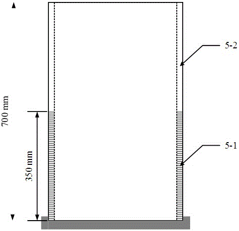
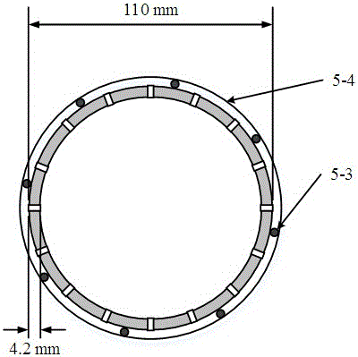
[0043] The equipment used in the indoor test of the present embodiment is as follows: Figure 5 As shown, the test container adopts an acrylic tube 6 with an outer diameter of 110 mm and a wall thickness of 5 mm. Place a 5cm thick permeable stone 9 to prevent the sample in the container from entering the constant water head column 7.

[0044] On the permeable stone 9 in the test container, first lay sulfur-containing tailings with a thickness of 10 cm and a particle size of -6 cm / s, the composite capping layer of this embodiment is laid on the sulfur-containing tailings.

[0045] Among them, the material used in the first sublayer of the composite capping layer is desulfurization gold mine tailings, the average diameter of ma...


PUM


Abstract

The invention belongs to the technical field of environmental geotechnics, and in particular, relates to a composite sealing cover structure of a sulfide-contained mine solid waste landfill field. The composite sealing cover structure of the sulfide-contained mine solid waste landfill field, realizing the purpose of the invention, consists of three composite sealing cover layers formed by three sublayers with different permeability coefficients, different matric suctions and different thicknesses; and a surface layer of the landfill field can keep enough water to realize reduction or elimination of air entering the internal of the landfill field so as to prevent formation of sulfide oxidation acid production conditions in the landfill field. The composite sealing cover structure also has the advantages of simple construction and low cost, and is more suitable for popularization in mining areas.

Description

technical field [0001] The invention belongs to the technical field of environmental geotechnical engineering, and in particular relates to a composite sealing structure for a sulfide-containing mine solid waste landfill. Background technique [0002] With the development of my country's mining and dressing industry and people's increasing awareness of environmental protection, the environmental pollution caused by the disposal of mine solid waste has become the focus of widespread attention. The development and utilization of mineral resources generally involves two processes: the mining and recovery process and the beneficiation and purification process. The mining recovery process refers to the process in which people use various methods and technologies to mine and recover the mineral resources stored in the ground to the ground. Affected by many factors such as the geological occurrence characteristics of mineral resources and the technologies used by people in their d...

Claims


Application Information

Patent Timeline
Patent Type & Authority Applications(China)
IPC IPC(8): B09B1/00
CPCB09B1/004
Inventor 姜利国尹成薇梁冰董擎秦冰王堃
Owner LIAONING TECHNICAL UNIVERSITY
Learn More