Power clamp for overhead lines

A technology for power line clips and overhead lines, applied in circuits, electrical components, conductive connections, etc., can solve problems such as poor firmness and easy loosening, and achieve the effects of reducing vibration, rational distribution of the center of gravity, and ensuring stability and reliability.

Inactive Publication Date: 2016-06-01
胡小青
View PDF4 Cites 1 Cited by
  • Summary
  • Abstract
  • Description
  • Claims
  • Application Information

AI Technical Summary

Problems solved by technology

However, the traditional power line clamps for overhead lines also have shortcomings. The pressure of clamping lines depends on the pressure of ordinary bolt components, which is poor in firmness and easy to loosen.

Method used


Image

  • Power clamp for overhead lines
  • Power clamp for overhead lines
  • Power clamp for overhead lines

Examples


Embodiment 1

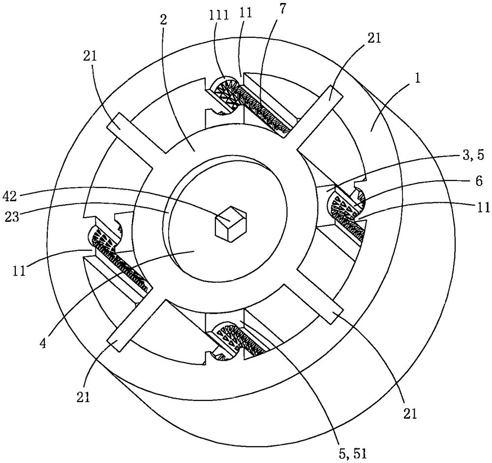
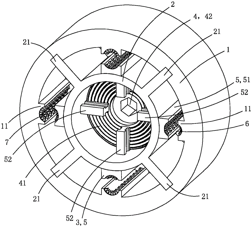
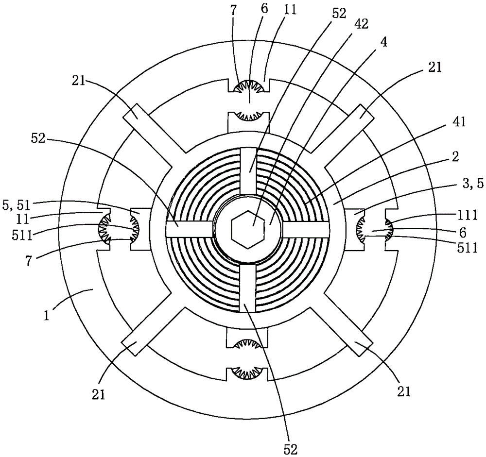
[0017] The present embodiment is a power line clamp for overhead lines, see Figure 1 to Figure 8 As shown, it includes a base tube 1, a core tube 2, a set of pressure jaw assembly 3 and a flat nut 4; the inner peripheral wall of the base tube is provided with a plurality of crimping bosses 11 along the axial direction of the base tube, and each crimping boss The inner wall of the platform is provided with an arc-shaped groove 111; the inner peripheral wall of the base tube is also provided with a plurality of positioning slide grooves 12 along the axial direction of the base tube; the outer peripheral wall of the core tube is provided with a plurality of supports extending radially along the base tube The convex plate 21, the outer end of each supporting convex plate is located in a corresponding positioning chute, thereby the core tube is supported and positioned in the lumen of the base tube; the core tube and the base tube are concentrically arranged and located in the lume...

Embodiment 2

[0029] This embodiment is basically the same as Embodiment 1, the difference is: see Figure 9 As shown, in this embodiment, a current transformer 8 is sleeved and fixed on the outer peripheral wall of the base pipe, and the number of the crimping bosses and claws is three, so this embodiment can form three clamping holes , for clamping the three phase cables. At this time, this embodiment as a whole can be used as a high-voltage zero-sequence current transformer to detect the existence of leakage current and find leakage faults in time.


PUM


Abstract

The invention discloses a power clamp for overhead lines. The power clamp comprises a base tube, a core tube, a set of compression claw component and a planar nut, wherein compression joint bosses are arranged on the inner circumferential wall of the base tube; radial limit sliding holes are formed in the tube wall of the core tube; an annular stopper is arranged on the inner circumferential wall of the core tube; the compression claw assembly comprises a plurality of compression claws; each compression claw comprises a compression plate part, a guide sliding block part and a drive threaded part; the planar nut is arranged in the tube cavity of the core tube in a rotating way and comprises a planar threaded part in engaged fit with the drive threaded part of each compression claw; the outer circumferential wall of the planar nut is adjacent to the inner wall of the core tube in a sliding way; one side end, adjacent to the stopper, of the planar nut is adjacent to the stopper in a sliding way; the planar threaded part is annular and is provided with Archimedes screw grooves; the planar nut drives the planar threaded part to rotate in a reciprocating way, so as to further drive all compression claws to get close mutually towards the center of the base tube or depart from each other. The power clamp for overhead lines has an excellent anti-loosening effect.

Description

technical field [0001] The invention belongs to the technical field of power fittings for overhead lines, and in particular relates to a power line clamp for overhead lines. Background technique [0002] In the construction of overhead power lines, when the cables need to be branched or spliced, it is necessary to connect two insulated conductors together with power line clamps for overhead lines. Power line clamps for overhead lines have the characteristics of easy installation, low cost, safety, reliability and maintenance-free. Cable branches can be made without cutting off the main cable or stripping the insulation layer of the cable. The joints are completely insulated and can be used for live work, and can be branched at any position on the cable; no terminal box or junction box is needed; and the joints are resistant to twisting, Shockproof, waterproof, anti-corrosion and aging; using insulated overhead lines and power line clamps as cable branches, the comprehensive...

Claims


Application Information

Patent Timeline
Patent Type & Authority Applications(China)
IPC IPC(8): H01R11/09H01R11/01H01R4/24H01R4/38
CPCH01R11/09H01R4/2408H01R4/38H01R11/01
Inventor 胡小青
Owner 胡小青
Why Eureka
Try Eureka