Alkaline zinc-manganese battery preventing liquid leakage caused by discharging due to application in series
A zinc-manganese battery, overdischarge technology, applied in dry batteries, primary batteries, battery pack components, etc., can solve the problem of reducing battery overdischarge depth, overdischarge leakage rate, uncontrolled overdischarge depth, and large battery gas evolution, etc. problems, to achieve the effect of reducing the probability of overdischarge leakage, reducing overdischarge leakage, and improving safety performance
- Summary
- Abstract
- Description
- Claims
- Application Information
AI Technical Summary
Problems solved by technology
Method used
Image
Examples
Embodiment 1
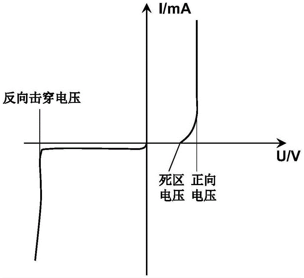
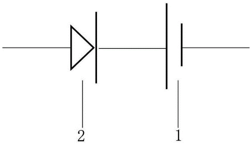
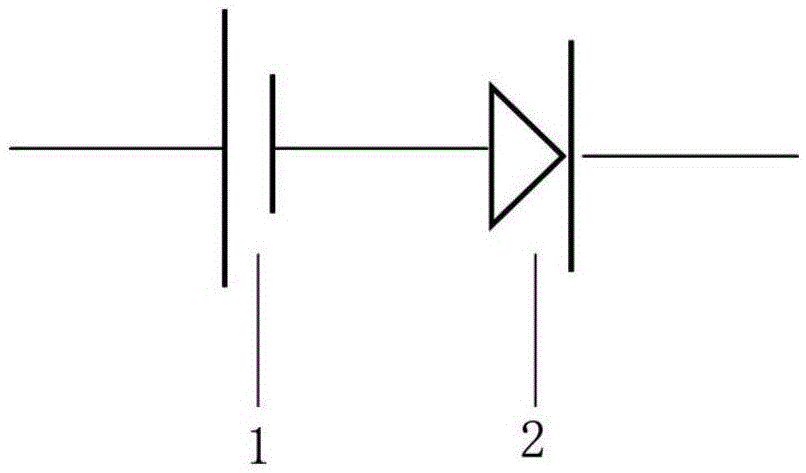
[0042] Embodiment 1: An alkaline zinc-manganese battery that prevents over-discharge and leakage due to series use, including a battery body 1, a semiconductor diode 2 is connected in series on the positive pole or negative pole of the battery body 1, and the dead zone voltage of the semiconductor diode is used to limit The lower limit of the voltage of the battery body during the discharge process to reduce the over-discharge depth of the battery body.
[0043] The battery body 1 includes a negative electrode bottom cover 11, a negative electrode copper nail 12 and a positive electrode false bottom 13. The chip semiconductor diode 2 is flatly attached to the outside of the negative electrode bottom cover 11, and the thickness of the chip semiconductor diode 2 is 0.5 mm or 2 mm or 5 mm. A nickel-plated steel sheet 3 is connected to the outside of the chip semiconductor diode 2 . Such as Figure 3a As shown, the semiconductor diode is a germanium semiconductor diode or a silic...
Embodiment 2
[0046] Embodiment 2: other parts are the same as Embodiment 1, and its difference is that the chip semiconductor diode 2 is flatly attached to the outside of the false bottom 13 of the anode, as Figure 3d shown.
Embodiment 3
[0047] Embodiment 3: Other parts are the same as in Embodiment 1, the difference is that the positive false bottom 13 is bonded to the positive end surface 14 of the steel shell by insulating glue, and the semiconductor diode 2 is installed with the positive false bottom 13 and the positive end surface 14 of the steel shell In the cavity between them, the semiconductor diode 2 is connected to the positive end surface 14 of the steel shell and the false bottom 13 of the positive electrode. Such as Figure 3c shown.
PUM
| Property | Measurement | Unit |
|---|---|---|
| thickness | aaaaa | aaaaa |
Abstract
Description
Claims
Application Information
 - Generate Ideas
- Intellectual Property
- Life Sciences
- Materials
- Tech Scout
- Unparalleled Data Quality
- Higher Quality Content
- 60% Fewer Hallucinations
Browse by: Latest US Patents, China's latest patents, Technical Efficacy Thesaurus, Application Domain, Technology Topic, Popular Technical Reports.
© 2025 PatSnap. All rights reserved.Legal|Privacy policy|Modern Slavery Act Transparency Statement|Sitemap|About US| Contact US: help@patsnap.com


