
Energy-saving power generation device capable of being additionally arranged on water pipe

An energy-saving power generation and water pipe technology, which is applied in hydropower generation, mechanical equipment, water supply main pipelines, etc., can solve the problems of water pipes not being fully utilized, no decompression device installed, water splashing on people, etc., and achieve simple structure , prevent pollution, solve the effect of excessive water pressure

Active Publication Date: 2016-06-01
SHAANXI UNIV OF SCI & TECH
View PDF9 Cites 3 Cited by
  • Summary
  • Abstract
  • Description
  • Claims
  • Application Information

AI Technical Summary

Problems solved by technology

[0003] 1) Defects of traditional faucets, after analysis, most of the traditional faucets use tap water, and there are some metal ions in the water, long-term accumulation will cause harm to the human body
[0004] 2) The function of traditional faucets is insufficient. Most of the faucets on the market are not equipped with decompression devices. When the water flow is large, the water pressure will be very high, and it is easy to splash water on people
[0005] 3) Who can not be fully utilized in the water pipe, resulting in waste

Method used


Image

  • Energy-saving power generation device capable of being additionally arranged on water pipe
  • Energy-saving power generation device capable of being additionally arranged on water pipe
  • Energy-saving power generation device capable of being additionally arranged on water pipe

Examples


Embodiment Construction

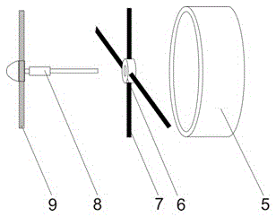
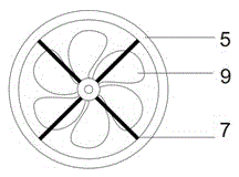
[0030] The structural principle and working principle of the present invention will be further described in detail below in conjunction with the accompanying drawings.

[0031] see figure 1 , 2, 4, a kind of energy-saving power generation equipment installed on the water pipe, including an insulating layer 2 arranged outside the water pipe, a pair of half-ring magnets 3 are arranged between the insulating layer 2 and the water pipe, and the ring magnet 3 is fixed to the water pipe 1 connection, the water pipe 1 is provided with a miniature power generation device; the transmission shaft 8 of the power generation device is threadedly connected with the fan blade 9, the transmission shaft 8 is connected with the rotor 12 through the bushing 6, and the rotor 12 is equipped with a brush 14, and the rotor 12 and the brush 14 is connected with the rotor supporting bushing 11 through the connection fixing frame 13, the rotor supporting bushing 11 is screwed with the copper sheet cont...


PUM


Abstract

An energy-saving power generation device capable of being additionally arranged on a water pipe comprises an insulation layer arranged outside the water pipe, a pair of semi-annular magnets is arranged between the insulation layer and the water pipe, and a micro power generation device body is arranged in the water pipe; a transmission shaft of the power generation device body is in threaded connection with fan blades, the transmission shaft is connected with a rotor through a shaft sleeve, an electric brush is arranged on the rotor, and the rotor and the electric brush are connected with a rotor supporting shaft sleeve through a connecting fixed support; the rotor supporting shaft sleeve is in threaded connection with a copper sheet contact, two wires are connected to the copper sheet contact, and the other ends of the two wires are connected with a storage battery through transmission openings; the shaft sleeve is in threaded connection with a shaft sleeve fixing support, and the shaft sleeve fixing support is connected with turbofan sleeves through pins; and water drives the fan blades to rotate while the water flows out, and the fan blades transmit power to a transmission shaft, so that the electric brush cuts a magnetic induction line generated by a large external magnet, and currents are generated; and the currents are stored in the storage battery through the wires, and the device has the beneficial effects of being simple in structure, environment-friendly, convenient to use and user-friendly in operation.

Description

technical field [0001] The invention relates to a self-generating device, in particular to an energy-saving generating device that can be installed on a water tap. Background technique [0002] After research, it is found that the existing faucet has the following defects: [0003] 1) Defects of traditional faucets. After analysis, most of the traditional faucets use tap water, and there are some metal ions in the water. Long-term accumulation will cause harm to the human body. [0004] 2) The function of traditional faucets is insufficient. Most of the faucets on the market are not equipped with decompression devices. When the water flow is large, the water pressure will be very high, and it is easy to splash water on people. [0005] 3) Who can not be fully utilized in the water pipe, resulting in waste. Contents of the invention [0006] In order to overcome the deficiencies of the above-mentioned prior art, the object of the present invention is to provide an energy-...

Claims


Application Information

Patent Timeline
IPC IPC(8): F03B13/10E03B7/09
CPCE03B7/09F03B13/10Y02E10/20
Inventor 贺雪梅鹿丹琼李志陈诚
Owner SHAANXI UNIV OF SCI & TECH
Learn More