
Automatic blowout device after oil and water well fracturing

A post-fracturing, oil-water well technology, applied in wellbore/well valve devices, wellbore/well components, and production fluids, etc., can solve the problem of easy stab damage, heavy workload, and poor gate closure safety accidents, etc. problems, to achieve the effect of avoiding workload, easy installation, and quick replacement

Inactive Publication Date: 2018-05-22
CHINA PETROLEUM & CHEM CORP +1
View PDF6 Cites 0 Cited by
  • Summary
  • Abstract
  • Description
  • Claims
  • Application Information

AI Technical Summary

Problems solved by technology

At present, oil and water wells are blown out after fracturing, and oil nozzles are manually installed in the blowout process to control the blowout pressure and flow rate. During the blowout process, the formation pressure needs to be observed at all times, and the size of the nozzles should be adjusted in time according to the pressure of the formation. , to prevent the formation pressure from falling too fast, resulting in formation sand spewing, fracturing cracks closed, affecting the fracturing effect
In addition, during the blowout process, due to the fracturing sand contained in the fracturing fluid, the scouring effect on the nozzle nozzle increases the aperture of the nozzle, and the well needs to be stopped frequently to replace the nozzle nozzle. The workload is heavy. The gate is easy to be damaged, and the gate is not closed tightly, which may cause safety accidents

Method used


Image

  • Automatic blowout device after oil and water well fracturing

Examples


Embodiment Construction

[0014] The detailed description and technical content of the present invention are described below with the accompanying drawings, but the accompanying drawings are only provided for reference and description, and are not intended to limit the present invention.

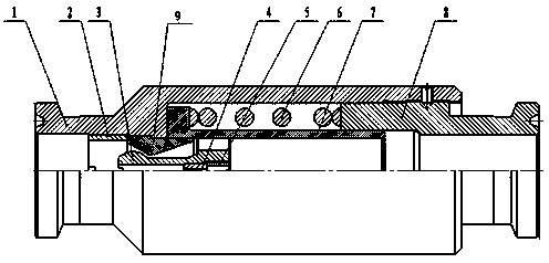
[0015] Such as figure 1 As shown, the automatic blowout device after oil-water well fracturing includes a valve body 1, a lower joint 8, and an automatic adjustment device. The valve body is connected to the lower joint. Return elastic movement mechanism, a valve core is set in the center cavity of the valve body, the outer side of the lower half of the valve core is connected to the automatic return elastic movement mechanism, the outer side of the upper half of the valve core 3 is spherical, corresponding to the upper end of the valve core The inner wall of the outer valve body 1 is fixed with a valve mouth 9, the inner side of the valve mouth is trumpet-shaped, a nozzle is formed between the outer wall of the valv...


PUM


Abstract

The invention discloses an automatic open flow device used after oil-water well fracturing. The automatic open flow device comprises a valve body, a lower connector and an automatic adjusting device. The valve body is connected with the lower connector. The automatic adjusting device comprises a valve core, a valve mouth and an automatic returning elastic moving mechanism. A center cavity of the valve body is provided with the valve core. The outside of the lower half part of the valve core is connected with the automatic returning elastic moving mechanism. The outside of the upper half part of the valve core is spheroidal. The valve mouth is fixed to the part, corresponding to the outside of the upper end of the valve core, of the inner wall of the valve body. The inner side of the valve mouth is in the trumpet shape. A nozzle is formed between the outer wall of the valve core and the inner wall of the valve mouth. A baffle is arranged at the bottom end inside the valve core. According to the automatic open flow device provided by the invention, site operation is simple, automatic open flow is conducted after oil-water well fracturing, the open flow quantity is automatically adjusted according to pressure, and the fracturing measure effect is ensured.

Description

technical field [0001] The invention relates to a blowout device in oil and natural gas recovery technology, in particular to an automatic blowout device after fracturing of an oil-water well. Background technique [0002] The implementation of fracturing measures in low-permeability reservoirs is an important means to transform oil-water well reservoirs. How to control the blowout of oil-water wells after fracturing construction is an important means to improve fracturing effects and protect oil layers. At present, oil and water wells are blown out after fracturing, and oil nozzles are manually installed in the blowout process to control the blowout pressure and blowout flow. During the blowout process, it is necessary to observe the formation pressure at all times, and adjust the size of the nozzle in time according to the pressure of the formation. , to prevent the formation pressure from falling too fast, causing the formation to spew out sand, and the fracturing cracks ...

Claims


Application Information

Patent Timeline
Patent Type & Authority Patents(China)
IPC IPC(8): E21B43/26E21B34/02
Inventor 庄栋秦延才王辉徐福刚迟洪利刘凤臣陈家乐赵法武
Owner CHINA PETROLEUM & CHEM CORP
Learn More