
Front auxiliary frame and engine suspension connecting structure

A technology of engine mount and front sub-frame, which is applied to the substructure, power unit, vehicle components, etc., can solve the problems of the fastening bolts being easily scratched and bruised by the protruding objects on the ground, the hidden danger of the vehicle and the occupants, etc. , to achieve the effect of being conducive to the balance of force, avoiding displacement and loosening, and high compressive strength

Active Publication Date: 2016-06-01
ZHEJIANG GEELY AUTOMOBILE RES INST CO LTD +1
View PDF8 Cites 8 Cited by
  • Summary
  • Abstract
  • Description
  • Claims
  • Application Information

AI Technical Summary

Problems solved by technology

[0005] The purpose of the present invention is to solve the problem that the fastening bolts in the existing connection structure between the front subframe and the engine mount are easily scratched and damaged by the protrusions on the ground, thereby causing potential safety hazards to the vehicle and passengers. Provides a connection structure between the front subframe and the engine mount with a simple structure, which can effectively protect the vehicle from scratching and colliding with the bolt heads connecting the engine mount and the front subframe when the vehicle is moving forward or backward. Conducive to improving the safety performance of vehicles

Method used


Image

  • Front auxiliary frame and engine suspension connecting structure
  • Front auxiliary frame and engine suspension connecting structure
  • Front auxiliary frame and engine suspension connecting structure

Examples


Embodiment Construction

[0030] The present invention will be further described below in conjunction with the accompanying drawings and specific embodiments.

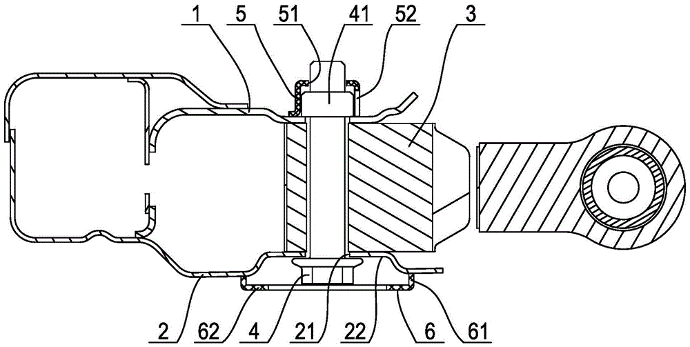
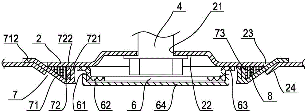
[0031] Such as figure 1As shown, a connection structure between a front subframe and an engine mount includes a subframe and an engine mount 3, the subframe includes an upper plate 1 of the subframe, a lower plate 2 of the subframe, and the engine mount 3 is provided Between the upper plate 1 of the subframe and the lower plate 2 of the subframe, the upper plate 1 of the subframe and the lower plate 2 of the subframe are made of sheet metal parts. The lower plate 2 of the sub-frame is provided with a bolt through hole 21 that vertically penetrates the engine mount 3 and the upper plate 1 of the sub-frame vertically upwards, and the fastening bolt 4 is passed through the bolt through hole 21 from bottom to top, and the fastening bolt 4 is fastened. The upper end of the bolt 4 protrudes from the bolt through hole 21 of the upper plate 1 of the s...


PUM


Abstract

The invention discloses a front auxiliary frame and engine suspension connecting structure. The connecting structure comprises an auxiliary frame upper plate, an auxiliary frame lower plate, and an engine suspension arranged between the auxiliary frame upper plate and the auxiliary frame lower plate; the auxiliary frame lower plate is provided with a bolt through hole upwards vertically penetrating through an engine suspension and the auxiliary frame upper plate; a fastening bolt extending out of a bolt through hole in the auxiliary frame upper plate is inserted in the bolt through hole from bottom to top; a protecting ring surrounding a bolt head of the fastening bolt is arranged on the lower side surface of the auxiliary frame lower plate; the protecting ring includes a cylindrical vertical ring connected with the auxiliary frame lower plate; and the lower edge of the vertical ring is inwards bent to extend to form a transverse reinforcing ring, so that the cross section of the protecting ring is L-shaped. The connecting structure is simple in structure, can effectively protect the bolt head for connecting the engine suspension with a front auxiliary frame from being scratched and collided by a ground projected object in advancement or retreating of a vehicle, and facilitates improvement of the vehicle driving safety.

Description

technical field [0001] The invention relates to the vehicle body structure, in particular to a connection structure between the front auxiliary frame and the engine suspension. Background technique [0002] The front sub-frame of the car is used as an intermediate transition connection part in the load-bearing body to provide support for the engine, and disperse and transmit the impact force from the ground and the engine to the body. The engine suspension is connected to the front sub-frame by bolts from bottom to top. Between the subframe upper plate and the subframe lower plate of the frame. For example, a "front 1 frame assembly structure" disclosed in Chinese patent literature, its announcement number is CN203601381U, includes the front sub-frame body, and the front sub-frame body includes the upper half shell of the body and the lower half shell of the body , the upper half shell of the body is fixedly connected with the lower half shell of the body, and one side of t...

Claims


Application Information

Patent Timeline
Patent Type & Authority Applications(China)
IPC IPC(8): B62D21/09B60K5/12
CPCB60K5/12B62D21/09
Inventor 宁强富邹新远胡思明刘海亮刘巍李力
Owner ZHEJIANG GEELY AUTOMOBILE RES INST CO LTD
Learn More