
An Intelligent Welding Seam System

An intelligent, welding torch technology, applied in welding equipment, auxiliary welding equipment, welding/cutting auxiliary equipment, etc., can solve the problems of lag in adjustment mode, poor accuracy, large error, etc., and achieve the effect of improving welding efficiency and reducing work intensity

Active Publication Date: 2017-12-01
江门健维自动化设备有限公司
View PDF8 Cites 0 Cited by
  • Summary
  • Abstract
  • Description
  • Claims
  • Application Information

AI Technical Summary

Problems solved by technology

The position of the welding seam and the adjustment of the welding torch during the welding operation can only be adjusted by manually observing the welding seam track and manually adjusting the welding torch fine-tuning cross mechanism. position, this adjustment method will lag and be inaccurate
[0007] 3. The sequence of each weld of the welded pipe row can only be manually moved by the workstation, and the welding sequence cannot be edited in advance
[0008] 4. 2 workstations require 2 operators to track and monitor in real time. It is necessary to manually adjust the adjustment handle of the welding torch and fine-tune the cross according to the actual welding seam position, so that the welding torch can reach the appropriate position, so that the workers are in a state of tension every minute and every second, and the load will increase significantly.
[0009] 5. The electrical control of the existing welding equipment is based on the PLC core, which cannot achieve precise positioning control, and the error is large; the product CAD graphics import function cannot be realized

Method used


Image

  • An Intelligent Welding Seam System
  • An Intelligent Welding Seam System
  • An Intelligent Welding Seam System

Examples


Embodiment Construction

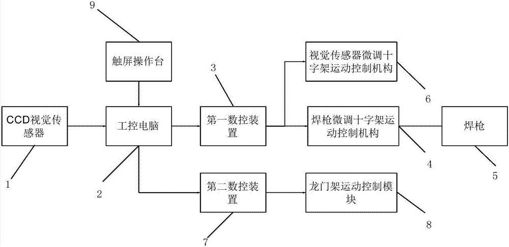
[0038] see figure 2 , which is a connection block diagram of the intelligent welding seam system of the present invention.

[0039] The invention provides an intelligent welding seam system, comprising a CCD visual sensor 1, an industrial computer 2, a first numerical control device 3, a welding torch fine-tuning cross movement control mechanism 4, a welding torch 5, a visual fine-tuning cross movement control mechanism 6, and a second numerical control device 7. Gantry motion control mechanism 8 and touch screen console 9.

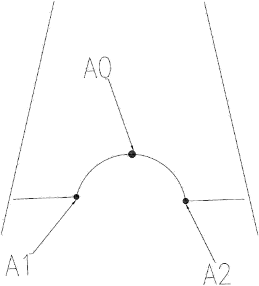
[0040] The CCD vision sensor 1 is used to scan the weld seam in real time, and send the scanning information to the industrial computer 2 . Please also see image 3 , which is a schematic diagram of a CCD vision sensor detecting a weld seam in the present invention. The CCD vision sensor 1 is located in the middle part A0 of the pipe or fin to be detected, and simultaneously detects the weld seam A1 and the weld seam A2 on both sides of the pipe or fi...


PUM


Abstract

The invention relates to an intelligent welding seam welding system. The intelligent welding seam welding system comprises a CCD vision sensor, an industrial control computer, a first numerical control device, a welding gun fine adjustment cross movement control mechanism and a welding gun. The CCD vision sensor is used for scanning a welding seam in real time and sending scanning information to the industrial control computer. The industrial control computer is used for conducting operation processing on the scanning information, generating welding gun movement track coordinates and transmitting the generated movement track coordinates to the first numerical control device. The first numerical control device sends a drive command to the welding gun fine adjustment cross movement control mechanism according to the received movement track coordinates. The welding gun fine adjustment cross movement control mechanism is used for controlling the horizontal movement, vertical movement and attitude angle rotary movement of the welding gun. Compared with the prior art, by means of the intelligent welding seam welding system, synchronous scanning and synchronous welding are achieved, no pre-scanning time exists, and the welding efficiency is improved to the maximum.

Description

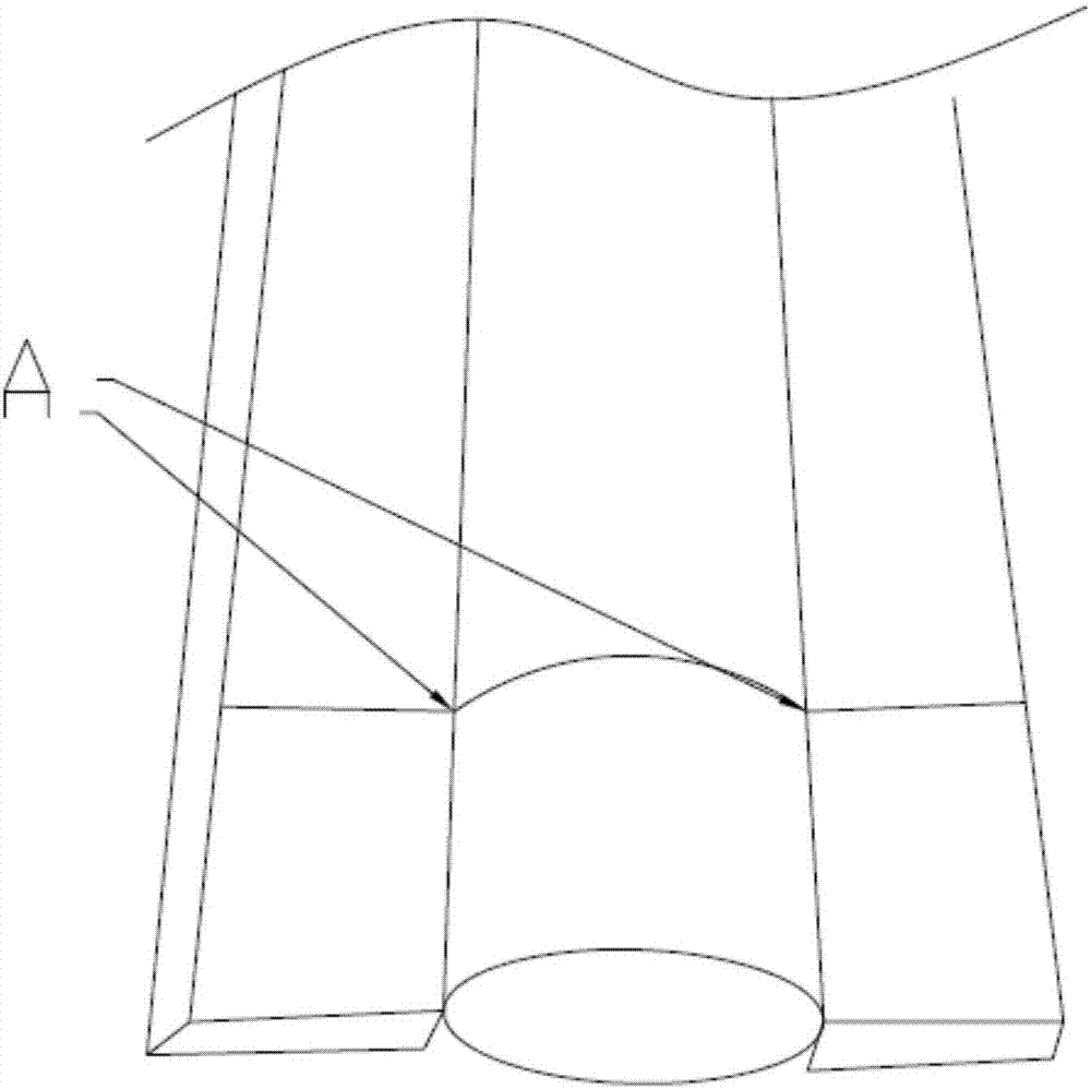
technical field [0001] The invention relates to a seam welding device, in particular to an intelligent seam welding system. Background technique [0002] In the power plant boiler and pressure vessel industry, it is necessary to carry out production and processing for the welding of tubes and fins. Such as figure 1 As shown, it is a schematic diagram of the weld between the tube and the fin. Among them, the gap between the two pipes is the weld A that needs to be welded. [0003] However, during the welding process of the existing machine welding equipment, the operator needs to observe the position of the weld seam all the time, and needs to manually adjust the welding torch in time and effectively, so that the welding torch can keep up with the welding seam track and ensure the welding quality. The manual observation of the weld track or the deviation of the weld cannot be accurately observed and predicted in advance. Even if it is manually adjusted, there will be probl...

Claims


Application Information

Patent Timeline
Patent Type & Authority Patents(China)
IPC IPC(8): B23K37/02
CPCB23K37/0247B23K37/0276
Inventor 卢育兵
Owner 江门健维自动化设备有限公司
Learn More