Shifting register unit, driving method, grid electrode driving circuit and display device

A shift register and gate drive technology, which is applied in the field of gate drive circuits, display devices, and shift register units, and can solve the problems of not being able to provide low pulse and high pulse light-emitting control signals at the same time

Active Publication Date: 2016-05-25
BOE TECH GRP CO LTD
View PDF6 Cites 14 Cited by
  • Summary
  • Abstract
  • Description
  • Claims
  • Application Information

AI Technical Summary

Problems solved by technology

[0003] The main purpose of the present invention is to provide a shift register unit, a driving method, a gate driving circuit and a display device, so as to solve the problem that a low-pulse gate driving signal and a high-pulse light-emitting control signal cannot be provided simultaneously in the prior art. Problems with shift register cells comprising a relatively small number of signal lines and transistors

Method used


Image

  • Shifting register unit, driving method, grid electrode driving circuit and display device
  • Shifting register unit, driving method, grid electrode driving circuit and display device
  • Shifting register unit, driving method, grid electrode driving circuit and display device

Examples


Embodiment Construction

[0067] The following will clearly and completely describe the technical solutions in the embodiments of the present invention with reference to the accompanying drawings in the embodiments of the present invention. Obviously, the described embodiments are only some, not all, embodiments of the present invention. Based on the embodiments of the present invention, all other embodiments obtained by persons of ordinary skill in the art without making creative efforts belong to the protection scope of the present invention.

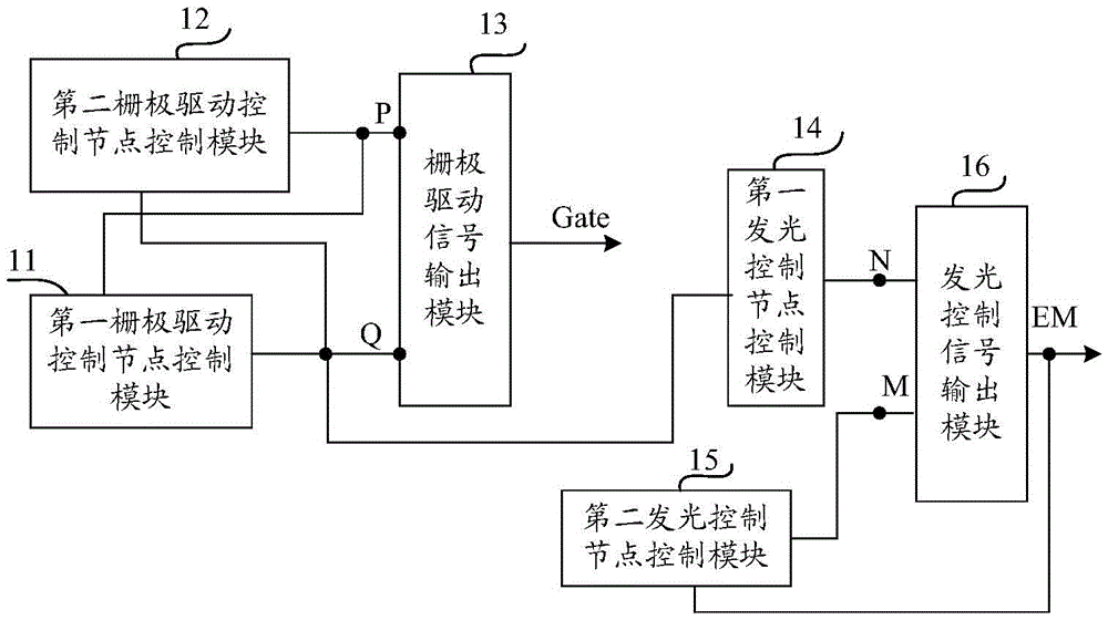
[0068] like figure 1 As shown, the shift register unit described in the embodiment of the present invention includes a gate drive signal output terminal Gate for outputting a gate drive signal and a light emission control signal output terminal EM for outputting a light emission control signal. The shift register The unit also includes:

[0069] The first gate drive control node control module 11 is respectively connected to the first gate drive control node ...


PUM


Abstract

The invention provides a shifting register unit, a driving method, a grid electrode driving circuit and a display device. The shifting register unit comprises a first grid electrode driving control node control module, a second grid electrode driving control node control module, a grid electrode driving signal output module, a first light-emitting control node control module, a second light-emitting control node control module and a light-emitting control signal output module, wherein the first light-emitting control node control module is used for controlling an electric potential of a first light-emitting control node to be a first electric potential under the control of a first grid electrode driving control node at an input phase and an output phase; and the second light-emitting control node control module is used for controlling the electric potential of a second light-emitting control node to be the first electric potential under the control of a light-emitting control signal at an output cutting-off keeping phase. According to the shifting register unit, the driving method, the grid electrode driving circuit and the display device, provided by the invention, the problem in the prior art that the shifting register unit which can provide a low-pulse grid electrode driving signal and a high-pulse light-emitting control signal at the same time, and comprises relatively few signal lines and transistors cannot be provided can be solved.

Description

technical field [0001] The present invention relates to the field of display technology, in particular to a shift register unit, a driving method, a gate driving circuit and a display device. Background technique [0002] In the field of display, in order to continuously improve the display screen, high ppi (PixelsPerInch, pixel density), narrow frame display has become a research hotspot. However, with the increase in the number of pixels, the number of rows that the gate drive circuit needs to scan in one frame time increases, and when the size of the display screen remains unchanged, the area of ​​the layout reserved for each row of shift register units gradually decreases. , In addition, the requirement of a narrow border makes the requirements of each row of shift register units more stringent, so a shift register circuit with a simple circuit structure and a small number of transistors is very necessary. And the prior art cannot provide a shift register unit including...

Claims


Application Information

Patent Timeline
IPC IPC(8): G09G3/20G11C19/28
CPCG09G3/20G09G2310/0286G11C19/28
Inventor 郑灿
Owner BOE TECH GRP CO LTD
Why Eureka
Try Eureka