
Oil-free vortex air compressor

An air compressor and scroll technology, applied in the field of oil-free scroll air compressors, can solve the problems of low reliability, impurities in the cooling air, environmental damage to the lubricating oil, etc., so as to reduce the ambient working temperature and keep the bearings lubricated. degree, the effect of increasing the heat dissipation area

Active Publication Date: 2016-05-25
GUANGDONG GANEY PRECISION MACHINE CO LTD
View PDF6 Cites 9 Cited by
  • Summary
  • Abstract
  • Description
  • Claims
  • Application Information

AI Technical Summary

Problems solved by technology

The design of the oil-injected air scroll compressor system is complex, and the compressed air with low oil content requires more cost, and the lubricating oil will cause environmental damage
[0004] The fins of the existing moving disk are limited by the space, and the heat dissipation area has not been fully utilized, so that the cooling effect is not ideal; the bearing and the bushing are in contact with each other, so that the heat is transferred to the bearing, which makes the bearing and its lubricating grease last for a long time. In the high temperature state, it leads to low reliability and shortened service life; in addition, there are the following problems: it is difficult to adjust the gap between the moving plate and the static plate, it is difficult to refill the bearings with grease, and there are impurities in the cooling air. In the machine, the wear of parts in the compressor is increased, and other problems exist in various aspects

Method used


Image

  • Oil-free vortex air compressor
  • Oil-free vortex air compressor
  • Oil-free vortex air compressor

Examples


Embodiment Construction

[0043] Embodiments of the present invention are described in detail below, examples of which are shown in the drawings, wherein the same or similar reference numerals designate the same or similar elements or elements having the same or similar functions throughout. The embodiments described below by referring to the figures are exemplary only for explaining the present invention and should not be construed as limiting the present invention.

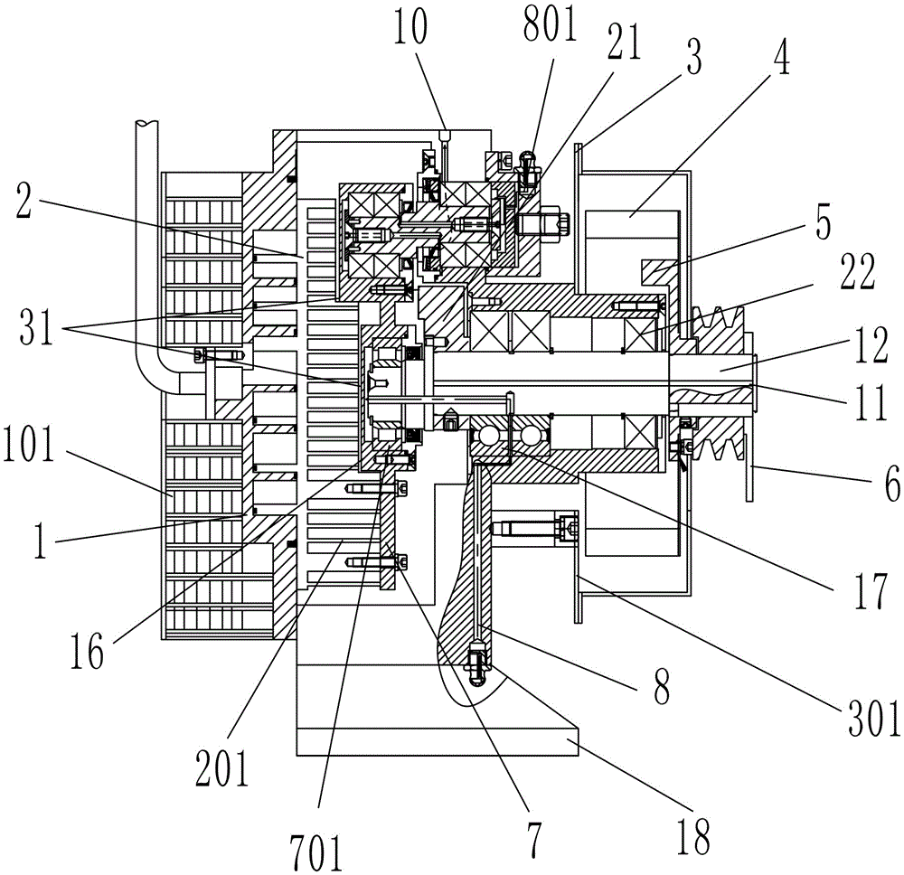
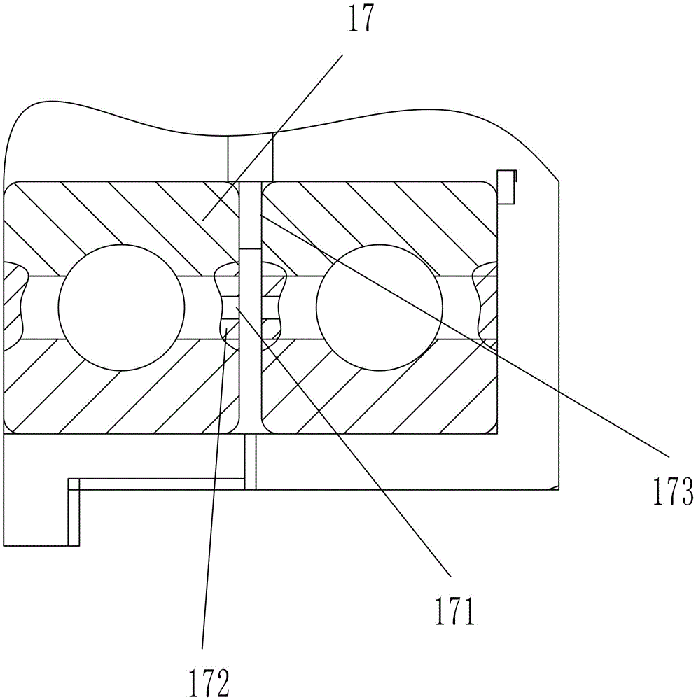
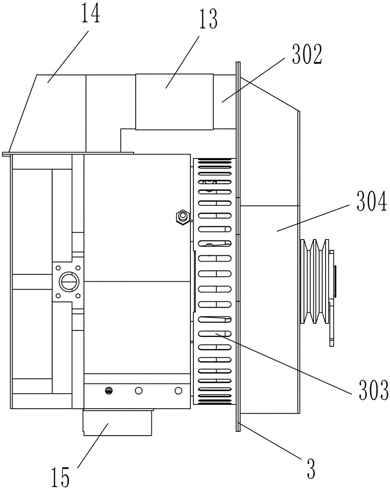
[0044] like Figure 1 to Figure 9As shown, an oil-free scroll air compressor described in the present invention includes a frame 18, a stationary disc 1, a moving disc 2, a bushing 7, a crankshaft 12 and a pin crank 9, and the stationary disc 1 is in contact with the end face of the frame 18. Cooperate installation, the moving plate 2 is installed in cooperation with the end face of the shaft sleeve 7 and is located in the frame 18, the second bearing 231 at one end of the pin crank 9 is installed on the frame 18, and the first bearing 2...


PUM


Abstract

The invention particularly relates to an oil-free vortex air compressor which comprises a rack, a static disc, a movable disc, a shaft sleeve, a crankshaft and pin cranks. The static disc is installed in the mode of being matched with the end face of the rack. The movable disc is installed in the mode of being matched with the end face of the shaft sleeve and located in the rack. A pin crank bearing at one end of each pin crank is installed on the rack, and a pin crank bearing at the other end of each pin crank is installed on the shaft sleeve. The shaft sleeve and the at least three pin cranks are restrained. The static disc and the movable disc driven by the crankshaft form a sealing cavity in continuous suction, compression and exhaust working states. Movable disc fins of a step type are arranged on the back of the movable disc. The shaft sleeve of a step type is installed on the movable disc fins. Clearance is reserved between all the bearing pedestal positions on the shaft sleeve and the movable disc fins. The air compressor has the advantages that the movable disc fins are utilized for being distributed on the back of the movable disc in a ladder shape, on the condition that the total length of the movable disc and the total length of the shaft sleeve is not changed, the heat dissipating area of the back of the movable disc is effectively increased, and the cooling effect is further achieved.

Description

technical field [0001] The invention specifically relates to the technical field of air compressors, in particular to an oil-free scroll air compressor. Background technique [0002] Scroll air compressors are widely used in industrial, agricultural, transportation and other industries where compressed air is needed due to their high efficiency, low noise, small size, high reliability, and benefits for energy saving and environmental protection. The main running part of the scroll air compressor is meshed with the scroll, which does not cause wear and tear, so the service life is longer than that of the piston and screw compressors, and it is an ideal power source for pneumatic machinery. In a scroll air compressor, the main parts are divided into a moving disk and a static disk, and the rotating disk and the static disk are provided with scroll plates. Usually, the moving disk and the static disk are combined to form a compression chamber. When the moving disk is driven b...

Claims


Application Information

Patent Timeline
IPC IPC(8): F04C18/02F04C29/04F04C29/00F04C29/02F04C29/06
CPCF04C18/0215F04C18/0253F04C29/00F04C29/0092F04C29/02F04C29/04F04C29/06
Inventor 陈伟成
Owner GUANGDONG GANEY PRECISION MACHINE CO LTD
Learn More