GAS mixing pump, particularly for heating system

A heating system, mixing pump technology, applied in control/regulation systems, air handling equipment, temperature control without auxiliary power supply, etc., can solve problems such as no pumping effect and no suction allowed

Inactive Publication Date: 2016-05-18
LIEBHERR AEROSPACE TOULOUSE
View PDF10 Cites 2 Cited by
  • Summary
  • Abstract
  • Description
  • Claims
  • Application Information

AI Technical Summary

Problems solved by technology

Furthermore, the system does not allow suction, so there is no pumping effect

Method used


Image

  • GAS mixing pump, particularly for heating system
  • GAS mixing pump, particularly for heating system
  • GAS mixing pump, particularly for heating system

Examples


Embodiment Construction

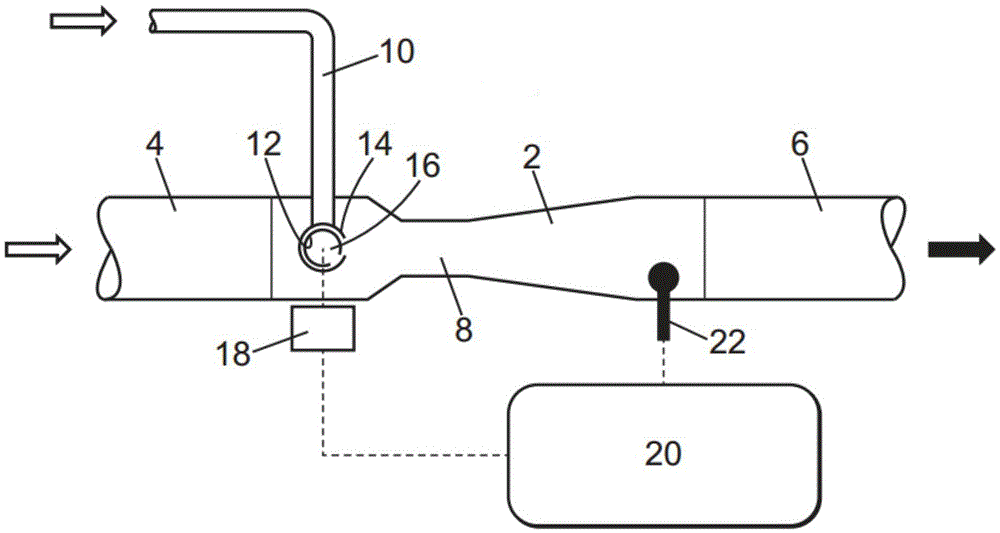
[0028] figure 1 The general structure of a preferred embodiment of a mixing pump 2 according to the present invention is explained.

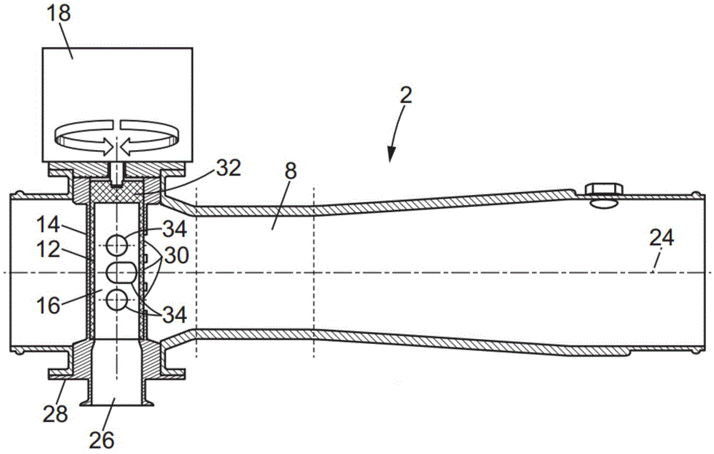
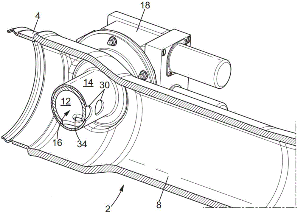
[0029] The mixing pump 2 shown is installed downstream of the cool air inlet 4 and upstream of the warm air outlet 6 . It comprises a main duct, a mixing section 8, a hot air inlet 10, and means for mixing the air flow from the cold air inlet 4 with the air flow directed by the hot air inlet 10 to the mixing pump 2 located in said main within the pipeline. The mixing tool includes a valve 12 disposed in a sleeve 14 and defining a chamber 16 .

[0030] An actuator 18 is provided for adjusting the position of the valve 12 in the sleeve 14. The actuator 18 is controlled by an acquisition and control system 20 , which is in particular associated with a temperature sensor 22 . The actuator 18 is preferably electrical. However, depending on the circumstances, it is also possible, for example, to have a pneumatic device with, for example, a single...


PUM


Abstract

A mixing pump (2) according to the invention comprises an air duct called as a cool air duct; an air intake (10) called as an hot air intake leading into the cool air duct; as well as means for injecting air from the hot air intake (10) into the cool air duct. The hot air intake (10) leads into a chamber (16) arranged at least partially in the cool air duct. The injection means have at least one opening (30), for connecting the inside of the chamber (16) to the inside of the cool air duct, and means (12) for modifying the flow area through the opening to at least one, connecting the inside of the chamber (16) to the inside of the cool air duct.

Description

technical field [0001] The invention relates to a gas mixing pump, especially a gas mixing pump used in a heating system. Background technique [0002] More specifically, the scope of the invention is the management of air in the cockpit or cabin of an aircraft (for simplicity, in the following, the cabin is used to refer to both), for example a helicopter, but also an airplane . To heat the cabin interior, it is known to harvest the hot air exiting the engines and extract unused calories to heat the cabin of the respective aircraft. [0003] The hot air exiting the engine cannot be used directly to heat the cabin. That air pressure is too high, and it's too hot to send it to the cabin as it is. Thus, this pressurized hot air is mixed with low pressure, low temperature cold air collected from outside the nacelle. [0004] Position control valves can be used to vary the temperature of the air injected into the nacelle. Such a valve is usually located on the hot air duct ...

Claims


Application Information

Patent Timeline
Patent Type & Authority Applications(China)
IPC IPC(8): G05D23/13F16K11/076B64D13/08
CPCB64D13/08G05D23/138G05D23/1393Y02T50/40
Inventor 安托伊内·佩雷
Owner LIEBHERR AEROSPACE TOULOUSE
Why Eureka
Try Eureka