
Digital synthetic aperture imaging method based on pupil modulation

An imaging method and synthetic aperture technology, applied in optics, optical components, instruments, etc., can solve problems such as high precision of mechanical structure and manufacturing process control, high system price, and poor applicability, so as to facilitate popularization and application, Simple and compact optical path, reducing complexity and cost

Active Publication Date: 2016-05-18
INST OF OPTICS & ELECTRONICS - CHINESE ACAD OF SCI
View PDF5 Cites 16 Cited by
  • Summary
  • Abstract
  • Description
  • Claims
  • Application Information

AI Technical Summary

Problems solved by technology

At present, the common phase detection technology proposed by scientists includes the detection technology based on the position information of interference fringes, the detection technology based on far-field image analysis, and the detection technology using special optical instruments. These technologies can realize the detection of translational phase errors under certain conditions. , but there are common defects, that is, the optical path used is complicated, the system is expensive, and the applicability is poor
Moreover, most of the correction methods adopted for the detected translational phase error are based on complex mechanical control, which have high requirements on mechanical structure, manufacturing process and control accuracy.

Method used


Image

  • Digital synthetic aperture imaging method based on pupil modulation
  • Digital synthetic aperture imaging method based on pupil modulation
  • Digital synthetic aperture imaging method based on pupil modulation

Examples


Embodiment

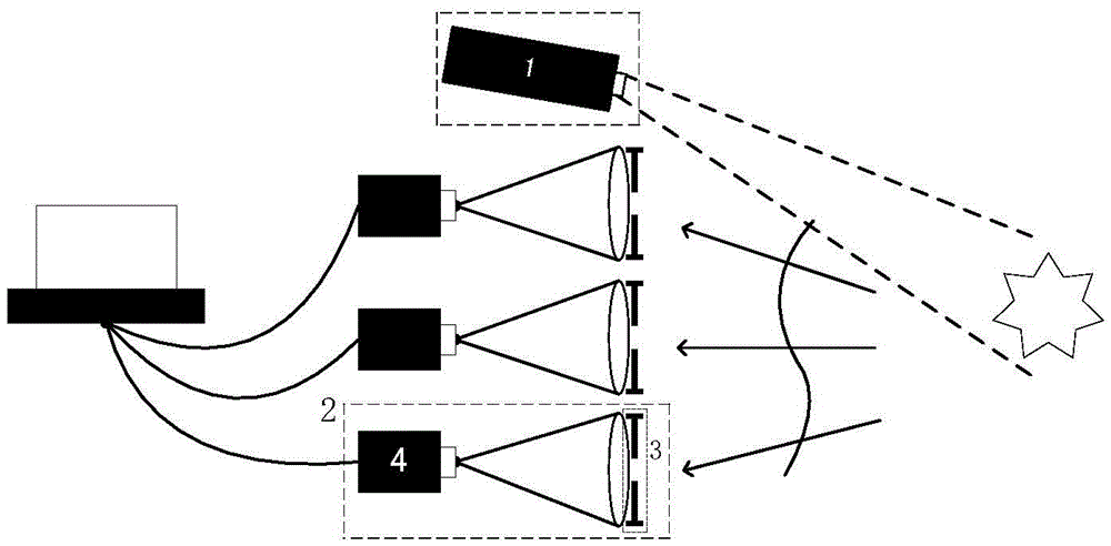
[0080] The entire synthetic aperture imaging system based on pupil modulation is composed of multiple sub-imaging systems, modulation diaphragms, CCD cameras and data processing terminals (generally using PCs). The working principle of the whole system is as follows: figure 1 Shown:

[0081] Its specific working process is:

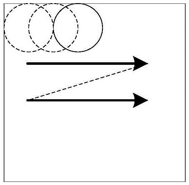
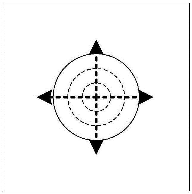
[0082] 1. For each sub-aperture system, when stack scanning modulation is used, such as figure 2 Control the clear aperture of the diaphragm as shown, and the CCD camera records the corresponding image; when the modulation of the aperture size is used, such as image 3 The aperture of the aperture is controlled as shown, and the corresponding image is recorded by the CCD.

[0083] 2. According to the modulation information (the position or size of the clear aperture) and the corresponding recorded image, use the FP algorithm to reconstruct the pupil light field at the data processing terminal.

[0084] 3. Perform digital processing on the light field ...


PUM


Abstract

The invention relates to a digital synthetic aperture imaging method based on pupil modulation. The digital synthetic aperture imaging method performs functions of restoring the optical field of the pupil, correcting single-aperture aberration, realizing multi-aperture common-phase, and obtaining high-resolution image through synthesis. According to the digital synthetic aperture imaging method, the pupil plane of each imaging subsystem is modulated by means of an external diaphragm; according to different modulation information (diameter, position or size of the light through hole of the diaphragm) and a corresponding image, reconstructing the optical field of each pupil by means of a Fourier ptychography algorithm; representing phase distribution of the optical field by means of a Zernike polynomial, optimizing a pixel evaluation function by means of a digital correction method, correcting an aberration of the single aperture and aberrations between multiple apertures, and combining pupil incoming optical fields for obtaining a high-resolution image based on a digital imaging principle. According to the digital synthetic aperture imaging method, optical field reconstruction, aberration correction and image synthesizing are combined. The digital synthetic aperture imaging method has advantages of high resolution of obtained image, compact optical path, simple device structure, low cost, etc.

Description

technical field [0001] The invention relates to a synthetic aperture imaging method, in particular to a new synthetic aperture imaging method based on pupil modulation, which uses a modulation diaphragm on the pupil surface of the subsystem to realize light field reconstruction, single aperture and multi-aperture aberrations Correction and synthesis imaging can reconstruct the light field of the pupil, and then digitally process the light field to correct aberrations, achieve sub-aperture co-phase, and synthesize high-resolution images. Background technique [0002] The optical synthetic aperture technology aims to use the easy-to-manufacture small-aperture system to synthesize a large-aperture system through optical means, so as to meet the high-resolution imaging requirements and solve the problem that the resolution is limited by the aperture size in practical applications. Synthetic aperture imaging techniques are generally divided into two types: baseline interferometri...

Claims


Application Information

Patent Timeline
Patent Type & Authority Applications(China)
IPC IPC(8): G02B27/58G02B27/00
CPCG02B27/0025G02B27/58
Inventor 谢宗良马浩统任戈亓波史建亮崔占刚谭玉凤王智鹏何小君董理
Owner INST OF OPTICS & ELECTRONICS - CHINESE ACAD OF SCI
Learn More