A Closed Elastic Core Adjusting Mechanism
A closed and elastic technology, applied in the direction of instruments, optics, light guides, etc., can solve the problems of insufficient adjustment accuracy, large structure volume, narrow adjustment range, etc., and achieve the effects of good stability, reduced processing difficulty, and convenient processing
- Summary
- Abstract
- Description
- Claims
- Application Information
AI Technical Summary
Problems solved by technology
Method used
Image
Examples
Embodiment 1
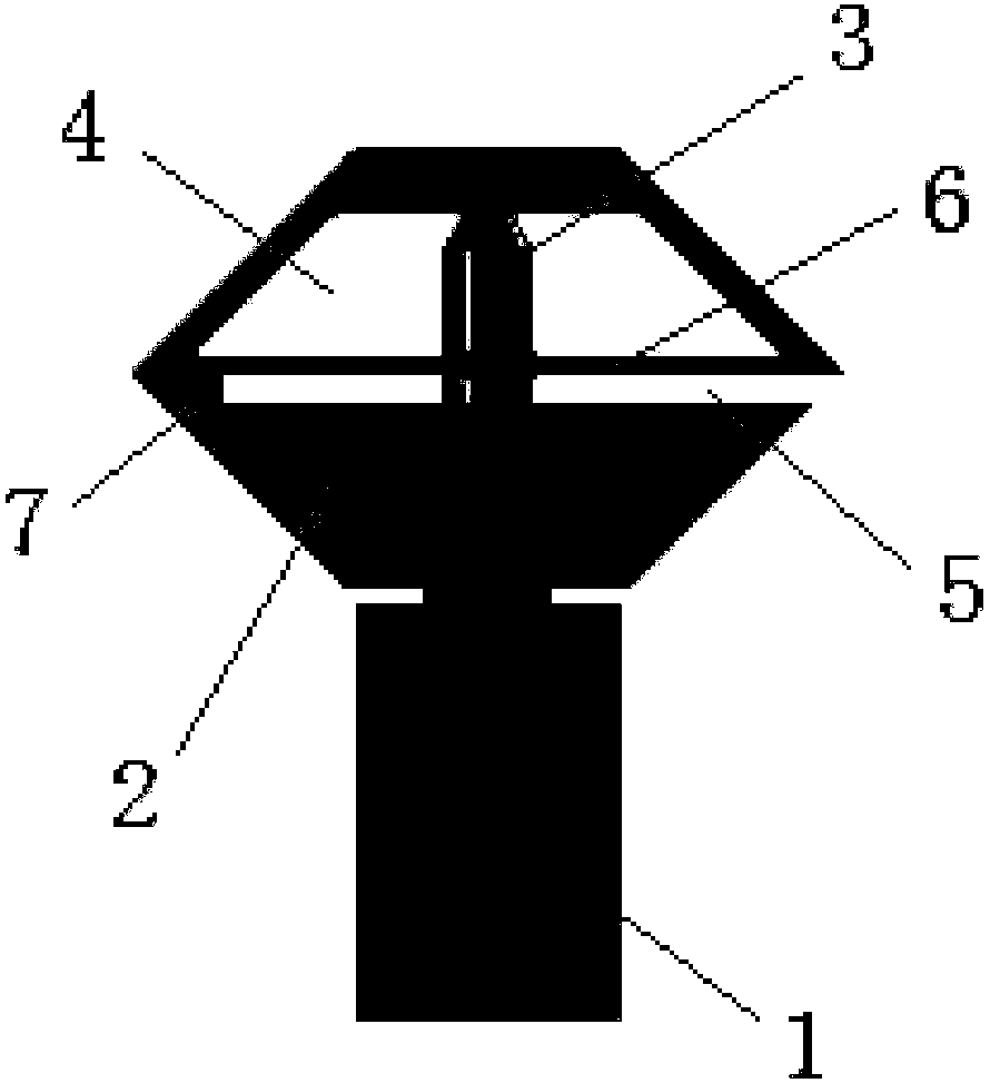
[0021] Such as figure 1 As shown, a closed elastic centering mechanism includes a bracket 1, a push rod 3 and an elastic body 2. The elastic body 2 is installed on the top of the bracket 1. It is characterized in that: the elastic body 2 is provided with a deformation cavity 4 and a deformation groove 5 , the deformation cavity 4 is a hollow and sealed cavity arranged above the interior of the elastic body 2, the deformation groove 5 is arranged under the deformation cavity 4, and there is a support wall 6 between the deformation cavity 4 and the deformation groove 5 to separate, and the ejector rod 3 is arranged Inside the elastic body 2 , the elastic bottom protrudes upwards and points to the deformation cavity 4 . When adjusting the centering, the extension of the ejector rod 3 squeezes the deformation chamber 4 to cause deformation. The deformation can help absorb the excessive adjustment of the ejector rod 3. At the same time, when the ejector rod 3 retracts, the deformat...
Embodiment 2
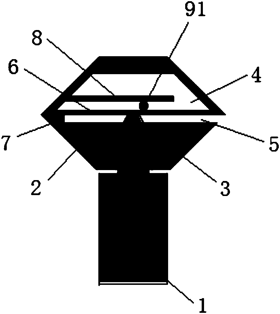
[0024] Such as figure 2 As shown, a closed elastic centering mechanism includes a bracket 1, a push rod 3 and an elastic body 2. The elastic body 2 is installed on the top of the bracket 1. It is characterized in that: the elastic body 2 is provided with a deformation cavity 4 and a deformation groove 5 , the deformation cavity 4 is a hollow cavity arranged above the interior of the elastic body 2, the deformation groove 5 is arranged under the deformation cavity 4, and there is a supporting wall 6 between the deformation cavity 4 and the deformation groove 5 to separate, and the ejector rod 3 is arranged on the elastic Inside the body 2, the elastic bottom protrudes upwards and points to the deformation cavity 4. When adjusting the centering, the extension of the ejector rod 3 squeezes the deformation chamber 4 to cause deformation. The deformation can help absorb the excessive adjustment of the ejector rod 3. At the same time, when the ejector rod 3 retracts, the deformatio...
Embodiment 3
[0027] Such as image 3 As shown, a closed elastic centering mechanism includes a bracket 1, a push rod 3 and an elastic body 2. The elastic body 2 is installed on the top of the bracket 1. It is characterized in that: the elastic body 2 is provided with a deformation cavity 4 and a deformation groove 5 , the deformation cavity 4 is a hollow cavity arranged above the interior of the elastic body 2, the deformation groove 5 is arranged under the deformation cavity 4, and there is a supporting wall 6 between the deformation cavity 4 and the deformation groove 5 to separate, and the ejector rod 3 is arranged on the elastic Inside the body 2, the elastic bottom protrudes upwards and points to the deformation cavity 4. When adjusting the centering, the extension of the ejector rod 3 squeezes the deformation chamber 4 to cause deformation. The deformation can help absorb the excessive adjustment of the ejector rod 3. At the same time, when the ejector rod 3 retracts, the deformation...
PUM
 Abstract
Description
Claims
Application Information
 - Generate Ideas
- Intellectual Property
- Life Sciences
- Materials
- Tech Scout
- Unparalleled Data Quality
- Higher Quality Content
- 60% Fewer Hallucinations
Browse by: Latest US Patents, China's latest patents, Technical Efficacy Thesaurus, Application Domain, Technology Topic, Popular Technical Reports.
© 2025 PatSnap. All rights reserved.Legal|Privacy policy|Modern Slavery Act Transparency Statement|Sitemap|About US| Contact US: help@patsnap.com


