Clamping mechanism for drop test machine

A technology of clamping mechanism and testing machine, which is applied in the direction of measuring device, impact test, machine/structural component test, etc. It can solve the problems of single drop test result and difficulty in adjusting the height of drop test

Active Publication Date: 2020-09-25
萍乡伊博智能科技有限公司
View PDF10 Cites 0 Cited by
  • Summary
  • Abstract
  • Description
  • Claims
  • Application Information

AI Technical Summary

Problems solved by technology

However, it is difficult for the above-mentioned electronic product drop test equipment to adjust the drop test height to meet the detection requirements of the product under test for various heights, and the drop test results are relatively single

Method used


Image

  • Clamping mechanism for drop test machine
  • Clamping mechanism for drop test machine

Examples


Embodiment Construction

[0021] The technical solutions of the present invention will be further described below in conjunction with the accompanying drawings and through specific implementation methods.

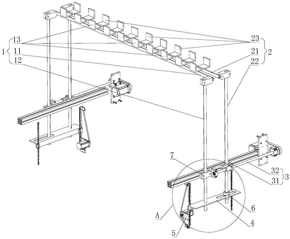
[0022] Such as figure 1 with figure 2As shown, a clamping mechanism for a drop tester provided in this embodiment includes a first clamping group 1, a second clamping group 2 and a horizontal feed mechanism 3, the first clamping group 1 and the second clamping group The two clamping groups 2 are distributed parallel to each other, the power output end of the horizontal feeding mechanism 3 is fixedly connected with the second clamping group 2, and the horizontal feeding mechanism 3 can drive the second clamping group 2 to perform a reciprocating feeding movement, and through the connection with the second clamping group 2 A clamping group 1 cooperates to clamp or loosen the sample to be tested. The horizontal feed mechanism 3 makes a horizontal feed movement, which can drive the second clamping gr...


PUM


Abstract

The invention discloses a clamping mechanism for a drop test machine. The invention belongs to the technical field of drop test. The nut end of a ball screw transmission set is fixedly connected withthe sliding block end of a guide rail sliding block set. A first clamping group is fixedly connected with the power output end of a lifting feeding mechanism through a mounting beam group. A second clamping group penetrates through the sliding block end of the guide rail sliding block set and is movably connected with the mounting beam group. The lifting feeding mechanism can drive the first clamping group and the second clamping group to do lifting reciprocating motion through the mounting beam group. The ball screw transmission set can drive the second clamping group to slide on the guide rail end of the guide rail sliding block set in a reciprocating mode through the sliding block end of the guide rail sliding block set, so that the second clamping group is matched with the first clamping group to clamp or loosen a sample to be tested. According to the clamping mechanism for a drop test machine disclosed by the invention, it is guaranteed that the clamping mechanism can stably and reliably achieve the clamping or loosening action, the clamping mechanism can adapt to to-be-tested sample machines of various sizes and specifications, batch drop detection can be conducted, and meanwhile the clamping height can be conveniently adjusted.

Description

technical field [0001] The invention relates to the technical field of drop testing, in particular to a clamping mechanism for a drop testing machine. Background technique [0002] All kinds of electronic products may be damaged due to accidents during use. Therefore, major brand manufacturers and component manufacturers around the world have increased product drop tests. Most of the damage to electronic products comes from drop collisions. R&D personnel often spend a lot of time and cost on product-related quality tests. The most common structural tests are drop and impact tests. [0003] Chinese Patent Publication No. CN209416640U discloses a drop testing machine, which includes a frame, a drop part, a test part and a receiving assembly, and the drop part is arranged on the frame to receive a drop sample, The testing part is movably arranged on the frame through a lifting device, and the testing part can move between a position flush with the falling part and a position a...

Claims


Application Information

Patent Timeline
Patent Type & Authority Applications(China)
IPC IPC(8): G01M7/08
CPCG01M7/08
Inventor 周礼信
Owner 萍乡伊博智能科技有限公司
Why Eureka
Try Eureka