
Multi-objective near-and-far field mixed source positioning method

A source location, multi-target technology, applied in the field of multi-target far and near-field mixed source location, can solve the problems of high computational complexity, poor anti-interference ability and noise robustness

Active Publication Date: 2016-05-18
JILIN UNIV
View PDF4 Cites 29 Cited by
  • Summary
  • Abstract
  • Description
  • Claims
  • Application Information

AI Technical Summary

Problems solved by technology

[0007] The invention provides a multi-target far-near-field mixed source positioning method, which is used to solve the problems of high computational complexity, poor anti-interference ability and noise robustness existing in the existing far-near-field mixed source positioning technology based on high-order statistics

Method used


Image

  • Multi-objective near-and-far field mixed source positioning method
  • Multi-objective near-and-far field mixed source positioning method
  • Multi-objective near-and-far field mixed source positioning method

Examples


Embodiment Construction

[0072] Include the following steps:

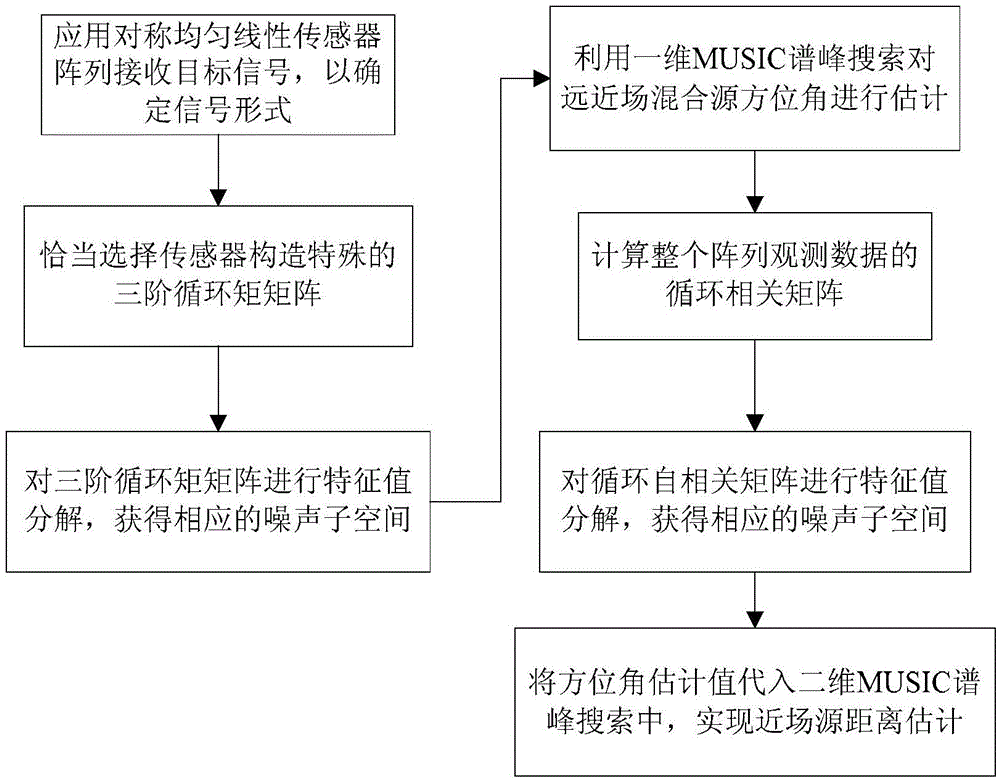
[0073] Step 1: Use a symmetrical uniform linear sensor array to receive the target signal, and determine the form of the far-near field mixed source observation signal;

[0074] Suppose M (including M 1 near-field sources and M-M 1 far-field sources) uncorrelated signal sources are incident on a symmetrical uniform linear array composed of L=2N+1 sensors, where d is the array element spacing and is equal in length, and array element 0 is used as a reference array element, then the lth The received signals of (1≤l≤L) sensors at time t can be expressed as

[0075]

[0076] where x l (t) is the sensor observation signal, s m (t) is the far-field source or near-field source envelope, n l (t) is the additive background noise of the sensor, M is the number of sources, is the angular frequency of the source signal, τ lm is the time delay difference from the reference array element to the lth sensor from the source m (1≤m≤M);

[0077] ...


PUM


Abstract

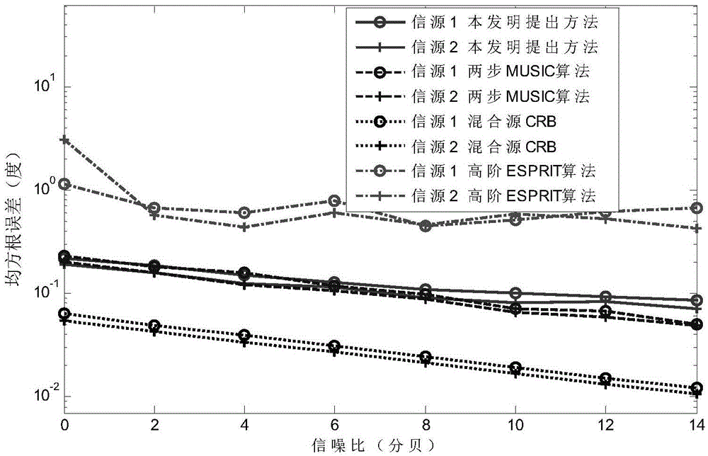
The invention provides a multi-target near-and-far field mixed source positioning method and belongs to the field of the array signal processing technology. According to the method, firstly, a symmetric and homogeneous linear sensor array is arranged to receive a target signal, and then the observation signal form of a near-and-far field mixed source is determined. Secondly, a special third-order cyclic matrix is constructed based on the output of a properly selected sensor, and a direction matrix thereof only contains the azimuth information of a far-field source and the azimuth information of a near-field source. Thirdly, the eigenvalue of the third-order cyclic matrix is decomposed, so that a corresponding noise sub-space is obtained. Fourthly, a cyclic autocorrelation matrix based on the observation data of the entire matrix is calculated, and the eigenvalue of the cyclic autocorrelation matrix is decomposed. In this way, a corresponding noise sub-space is obtained. Fifthly, an already estimated azimuth is substituted to the two-dimensional MUSIC spectrum peak searching process, so that the estimation on the distance of the near-field source is realized. The application of four-order cumulants is avoided, and the calculation complexity of the algorithm is effectively reduced. The operation time of the algorithm is shortened. Meanwhile, the cyclic steady interference and the steady background noise are effectively suppressed. Moreover, the extra parameter matching process is avoided.

Description

technical field [0001] The invention belongs to the field of array signal processing, and in particular relates to a multi-target far-near-field mixed source positioning method. Background technique [0002] Passive source location parameter estimation is the main research content in the field of array signal processing, which has important research significance and practical application value. According to the distance between the positioning target and the receiving sensor array, the traditional source location technology can be divided into far-field source location and near-field source location. However, in some practical applications, such as when using a microphone array to locate the speaker, the target signal may be located in the Fraunhofer (Fraunhofer) area of ​​the array aperture, or in the Fresnel (Fresnel) area of ​​the array aperture, That is, the array observation signal is composed of far-field sources and near-field sources. In essence, both the far-field...

Claims


Application Information

Patent Timeline
IPC IPC(8): G01S5/02
CPCG01S5/0257
Inventor 孙晓颖刘国红陈若男陈建燕学智
Owner JILIN UNIV
Learn More