
Scroll compressor

A scroll compressor and moving scroll technology, applied in the field of compressors, can solve problems such as low oil discharge rate, achieve the effects of reducing friction and wear, reducing exhaust noise, and flexible design

Active Publication Date: 2016-05-18
GUANGDONG MIDEA ENVIRONMENTAL TECH CO LTD +1
View PDF8 Cites 14 Cited by
  • Summary
  • Abstract
  • Description
  • Claims
  • Application Information

AI Technical Summary

Problems solved by technology

[0006] The technical problem to be solved by the present invention is that in the prior art, while lubricating the surface of the end plate between the movable and static scrolls, it is impossible to have a low oil discharge rate at the same time

Method used


Image

  • Scroll compressor
  • Scroll compressor
  • Scroll compressor

Examples


Embodiment 1

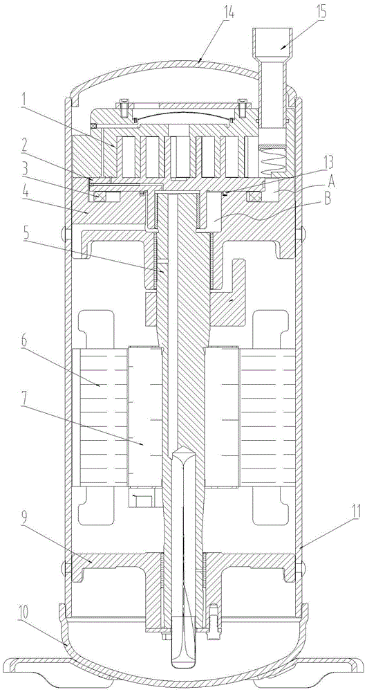
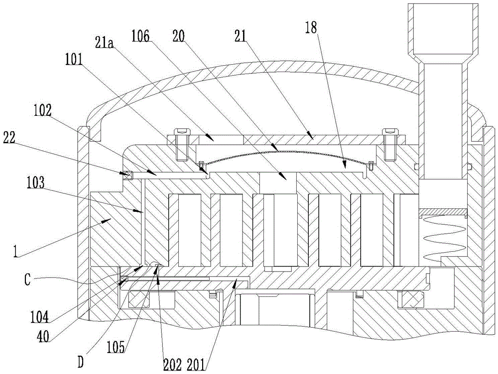
[0040] Such as Figure 1-4 As shown, the scroll compressor provided in this embodiment includes a fixed scroll 1 and a movable scroll 2; a compression chamber for compressing refrigerant is formed between the fixed scroll 1 and the movable scroll 2, and the fixed scroll The exhaust area of ​​the disk 1 is provided with an exhaust buffer chamber 18 connected with the compression chamber, and an oil-gas separation device 20 is provided in the exhaust buffer chamber 18, and the refrigerant discharged from the compression chamber first enters the exhaust buffer chamber 18, and then passes through the oil-gas The separation device 20 separates oil and gas, and the separated lubricating oil falls to the bottom of the exhaust buffer chamber 18 . At the same time, at the end plate surface where the fixed scroll 1 and the movable scroll 2 are attached and located at the periphery of the compression chamber (the horizontal bonding of the fixed scroll 1 and the movable scroll 2 at the pe...

Embodiment 2

[0060] Such as Figure 5-7 As shown, the technical content of the second embodiment is the same as that of the first embodiment and will not be described repeatedly. The content disclosed in the first embodiment also belongs to the content disclosed in the second embodiment. The difference between the second embodiment and the first embodiment lies in the following points:

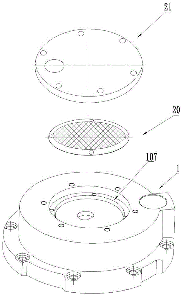
[0061] In this embodiment, the oil-gas separation device 20 is a filtering orifice plate, and the filtering orifice plate is a hemispherical orifice structure with the center protruding upward. The filtering orifice plate has a plurality of through holes 20a, which can be directly stamped from a thin metal plate. Certainly, the oil-gas separation device 20 may also be made of other materials having the function of oil-gas separation.

[0062] In this embodiment, the first oil groove 104 and the second oil groove 105 are respectively opened on the end plate surface of the movable scroll 2, which also have ...


PUM


Abstract

The invention relates to the technical field of compressors, in particular to a scroll compressor. The scroll compressor comprises a fixed scroll and an orbiting scroll, wherein an exhaust buffering cavity which is connected with a compressing cavity is formed in an exhaust region of the fixed scroll; an oil-gas separating device is arranged in the exhaust buffering cavity; at least one first oil groove and at least one second oil groove are formed in an end plate surface, which is attached to the orbiting scroll, of the fixed scroll and are positioned in the periphery of the compressing cavity; the first oil grooves are connected with the bottom of the exhaust buffering cavity through a first channel; and the second oil grooves are connected with a bearing hole of the orbiting scroll through a second channel. By the scroll compressor, the problem that low oil drainage rate cannot be realized while the end plate surface between the orbiting scroll and the fixed scroll is lubricated in the prior art is solved effectively.

Description

technical field [0001] The invention relates to the technical field of compressors, in particular to a scroll compressor. Background technique [0002] Scroll compressors are widely used in systems such as air conditioners and heat pumps because of their high efficiency, small size, light weight, and smooth operation. In the scroll compressor, a series of crescent-shaped compression chambers are formed by the meshing of the spiral lines on the movable scroll and the fixed scroll. With the eccentric operation of the movable scroll, the crescent-shaped compression chambers continue from the periphery At this time, the refrigerant in the compression chamber is pushed to the center, its volume decreases and the pressure continues to rise until it communicates with the exhaust port of the central static disk, and the refrigerant becomes high-pressure gas and is discharged from the compression chamber to complete the compression process. During the operation of the compressor, t...

Claims


Application Information

Patent Timeline
Patent Type & Authority Applications(China)
IPC IPC(8): F04C18/02F04C29/02F04C29/00
CPCF04C18/0215F04C29/00F04C29/026F04C2220/20
Inventor 梁卫恒
Owner GUANGDONG MIDEA ENVIRONMENTAL TECH CO LTD
Learn More