
Electromagnetic briquetting machine

A briquetting machine, electromagnetic technology, applied in punching machines, presses, presses using rotating pressure components, etc., can solve problems such as work efficiency limitations, long reciprocating strokes of hydraulic rods, bursting, etc., to reduce the occupied space, mechanical The overall compactness and the effect of improving the service life

Active Publication Date: 2016-05-18
江苏百代节能建材有限公司
View PDF5 Cites 1 Cited by
  • Summary
  • Abstract
  • Description
  • Claims
  • Application Information

AI Technical Summary

Problems solved by technology

[0002] Briquetting machine, a commonly used machine in mechanical processing; a large amount of chips are often produced in the process of mechanical processing. In order to facilitate storage and transportation, the chips are often concentrated and pressed into shape; the common briquetting machine is powered by a hydraulic system. When the hydraulic cylinder appears When it is damaged, it is prone to harmful explosions, which seriously threaten the safety of the staff; the traditional hydraulic system is large in size, and the reciprocating stroke of the hydraulic rod is long during press-fitting, which occupies a large processing site. At the same time, the working efficiency is limited by the stroke; in addition, the safety pressure provided by the hydraulic system is limited, and some hard materials cannot be firmly pressed, which makes the pressing block difficult to transport , easy to break during stacking, etc.

Method used


Image

  • Electromagnetic briquetting machine
  • Electromagnetic briquetting machine

Examples


Embodiment

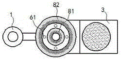
[0014] exist figure 1 In the illustrated embodiment, the electromagnetic briquetting machine includes a feed end 1, a press bin 2 and a conveyor belt 3; the feed end 1 is installed on the side wall of the press bin 2; The bottom side wall of the loading bin 2 is provided with a discharge end 4, and the discharge end 4 is engaged with the conveyor belt 3; A discharge plate 21, the discharge plate 21 is controlled by the mechanical arm 211 to reciprocate; the upper half of the inner wall of the press-loaded warehouse 2 is provided with a pressurized thread; A pressurizing screw 5, the pressurizing screw 5 is matched with the pressurizing thread; the material hardness of the pressurizing screw 5 is less than the material hardness of the sidewall of the press-fitting bin 2; at the bottom of the pressurizing screw 5 A pressure piece 51 is installed, the pressure piece 51 is coaxial with the pressure screw 5, and the pressure piece 51 can rotate freely relative to the pressure scre...


PUM


Abstract

The invention relates to an electromagnetic briquetting machine. The electromagnetic briquetting machine comprises a feeding end, a press-fitting bin and a conveying belt. A discharging plate is arranged at the position, directly facing the discharging end, of the side wall of the press-fitting bin; a pressurizing screw rod is further arranged on the upper portion of the press-fitting bin, and a conducting strip is fixedly mounted at the upper end of the pressurizing screw rod; conducting columns are rotatably and symmetrically distributed on the conducting strip, and a conducting ring is fixed to the upper end of each conducting column; the conducting rings and the conducting strip can be driven by the conducting columns to synchronously rotate; the conducting strip is connected with the positive electrode and the negative electrode of a direct-current power source, and the conducting rings are connected with the positive electrode and the negative electrode of the direct-current power source; an inner permanent magnet cylinder is arranged on the inner rings of the conducting rings, and an outer permanent magnet cylinder is mounted on the outer rings of the conducting rings; and the opposite cylinder faces of the inner permanent magnet cylinder and the outer permanent magnet cylinder are in heteropole attraction. The electromagnetic briquetting machine is compact in structure, small and exquisite in size, capable of carrying out efficient press fitting on chippings and suitable for press fitting of multiple kinds of chippings.

Description

technical field [0001] The invention relates to a mechanical processing device, in particular, a briquetting machine. Background technique [0002] Briquetting machine, a commonly used machine in mechanical processing; a large amount of chips are often produced in the process of mechanical processing. In order to facilitate storage and transportation, the chips are often concentrated and pressed into shape; the common briquetting machine is powered by a hydraulic system. When the hydraulic cylinder appears When it is damaged, it is prone to harmful explosions, which seriously threaten the safety of the staff; the traditional hydraulic system is large in size, and the reciprocating stroke of the hydraulic rod is long during press-fitting, which occupies a large processing site. At the same time, the working efficiency is limited by the stroke; in addition, the safety pressure provided by the hydraulic system is limited, and some hard materials cannot be firmly pressed, whic...

Claims


Application Information

Patent Timeline
Patent Type & Authority Applications(China)
IPC IPC(8): B30B1/42B30B3/00
Inventor 胡振强
Owner 江苏百代节能建材有限公司
Learn More