
Circuit and method for resonant network

A resonant network and resonance technology are applied in the field of circuits and methods of resonant networks, and can solve the problems of high switching signal frequency, large switching loss, and narrow power adjustment range.

Active Publication Date: 2016-05-11
GE LIGHTING SOLUTIONS LLC
View PDF7 Cites 7 Cited by
  • Summary
  • Abstract
  • Description
  • Claims
  • Application Information

AI Technical Summary

Problems solved by technology

[0005] However, a fixed LCC resonant network is not suitable for all kinds of LED arrays
In some cases, when the LED array is dimmed, the switching signal frequency is too high, resulting in large switching losses
In some cases, although the frequency of the switching signal is in a large range, the power adjustment range is very narrow

Method used


Image

  • Circuit and method for resonant network
  • Circuit and method for resonant network
  • Circuit and method for resonant network

Examples


Embodiment Construction

[0019] Unless otherwise defined, the technical terms or scientific terms used in the specification and claims shall have the ordinary meanings understood by those skilled in the technical field to which the present invention belongs. "First" or "second" and similar words used in the specification and claims do not indicate any order, quantity or importance, but are only used to distinguish different components. Words such as "a" or "a" and the like do not denote a limitation of quantity, but indicate that there is at least one, and unless otherwise stated, are used for convenience of expression only and are not limited to any position or spatial orientation.

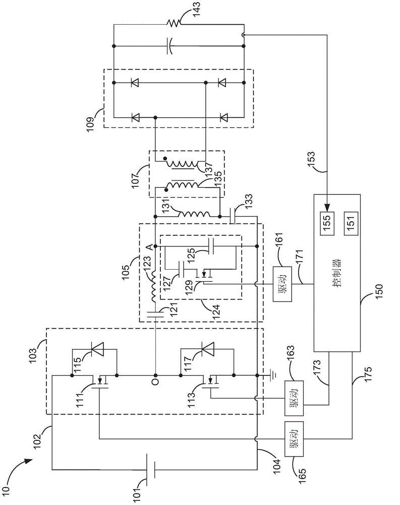
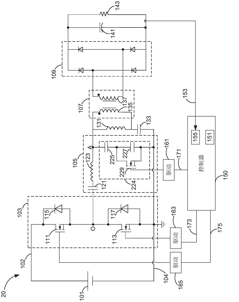
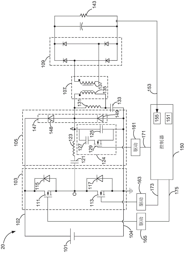
[0020] Please refer to figure 1 , is a schematic diagram of an embodiment of the power conversion circuit 10 of the present invention. The power varying circuit 10 includes a square wave generator 103 , a resonant network 105 , a transformer 107 , a rectifier 109 and a controller 150 .

[0021] The square wave generato...


PUM


Abstract

The invention discloses a circuit and a method for a resonant network, and specifically discloses a power conversion circuit. The power conversion circuit comprises a square wave generator, a resonant network, a transformer and a controller. The square wave generator is used for generating a square wave power. The resonant network is used for receiving the square wave power and outputting a first resonance power. The resonant network is composed of a capacitor, an inductor and a controllable capacitive device. The transformer is connected with the controllable capacitive device, and is used for receiving the first resonance power and outputting a second resonance power. The second resonance power after rectification is supplied to a load. The controller is used for generating an on-off signal based on the result of comparison between a threshold signal and a signal calculated according to at least one detection signal of the load, and supplying the on-off signal to the controllable capacitive device.

Description

technical field [0001] The disclosed embodiments of the present invention relate to circuits and methods for expanding the power adjustment range of a power conversion circuit, and in particular to circuits and methods for using a controllable capacitive device in a resonant network of a power conversion circuit. Background technique [0002] Power conversion circuits are widely used in various fields, such as communications, lighting, automobiles, military industry, etc., to provide appropriate power. In order to meet the requirements of low power consumption and energy saving, some resonant networks are often used in power conversion circuits. For example, an LC resonant network, an LLC resonant network or an LCC resonant network can help make the power changing circuit work more efficiently and have a larger power adjustment range. [0003] As far as light emitting diodes (Light Emitting Diode, LED) are concerned, a dimming function can be realized by utilizing a wide po...

Claims


Application Information

Patent Timeline
Patent Type & Authority Applications(China)
IPC IPC(8): H02M3/335H05B37/02
CPCH02M3/3376H02M1/0058H02M7/4818Y02B70/10
Inventor 拉马努金·拉玛班德兰詹保罗·卡利毛赛君
Owner GE LIGHTING SOLUTIONS LLC
Learn More