Energy-saving transformer
An energy-saving transformer and transformer oil technology, applied in the direction of transformer/inductor cooling, transformer/inductor magnetic core, etc., can solve the problems of increasing the complexity of transformer structure, unfavorable transformer oil sufficient sealing, and overall cost increase, so as to achieve good environmental protection effect, noise reduction, and effect of improving transformation efficiency
- Summary
- Abstract
- Description
- Claims
- Application Information
AI Technical Summary
Problems solved by technology
Method used
Image
Examples
Embodiment 1
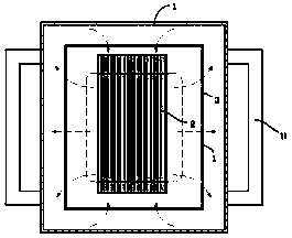
[0014] exist figure 1 , figure 2 In the first embodiment shown, the energy-saving transformer includes a housing 1, the surrounding wall of the housing 1 is distributed with cooling fins 11, the inside of the housing is filled with transformer oil, and the inside of the housing 1 is fixed with an iron core 2 formed by stacking silicon steel sheets; The iron core 2 is surrounded by an iron core box 3 surrounded by heat-conducting walls; and each heat-conducting wall of the iron core box 3 is a one-way flow wall, wherein two heat-conducting walls parallel to the silicon steel sheet , the flow direction is from the inside of the core box 3 to the outside of the core box 3; the flow direction of the other four heat-conducting walls is from the outside of the core box to the inside of the core box.
[0015] In the first embodiment, the heat conduction wall is as figure 2 As shown, it includes a fixed porous plate 311, a movable porous plate 312, and a fixed mesh plate 313 paral...
Embodiment 2
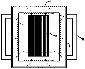
[0018] exist image 3 In the shown embodiment 2, the energy-saving transformer includes a housing 1, the surrounding wall of the housing is distributed with cooling fins 11, the inside of the housing 1 is filled with transformer oil, and the inside of the housing is fixed with an iron core 2 formed by stacking silicon steel sheets; The iron core 2 is surrounded by an iron core box 3 surrounded by heat-conducting walls; In this way, under the same pressure conditions, the amount of liquid flowing from the large mouth end of the conical punching hole to the small mouth end will be significantly greater than the liquid volume flowing from the small mouth end to the large mouth end; it is advisable to set the side where the large mouth end of the tapered punching hole is located as The side A of the heat conduction wall, the side where the small mouth end is located is the side B of the heat conduction wall; then in the second embodiment, the two heat conduction walls parallel to ...
PUM
| Property | Measurement | Unit |
|---|---|---|
| thickness | aaaaa | aaaaa |
Abstract
Description
Claims
Application Information
 - R&D
- Intellectual Property
- Life Sciences
- Materials
- Tech Scout
- Unparalleled Data Quality
- Higher Quality Content
- 60% Fewer Hallucinations
Browse by: Latest US Patents, China's latest patents, Technical Efficacy Thesaurus, Application Domain, Technology Topic, Popular Technical Reports.
© 2025 PatSnap. All rights reserved.Legal|Privacy policy|Modern Slavery Act Transparency Statement|Sitemap|About US| Contact US: help@patsnap.com


