
On-chip impedance matching method of ultrahigh frequency radio frequency identification electronic tag chip

A technology of electronic tags and radio frequency identification, which is applied to record carriers used in machines, instruments, computer components, etc. It can solve problems such as not working well, high antenna Q value, and affecting the normal operation of tags, so as to ensure high stability. and reliability, increased capacitance density, and low cost effects

Active Publication Date: 2016-05-11
睿芯联科(北京)电子科技有限公司
View PDF4 Cites 1 Cited by
  • Summary
  • Abstract
  • Description
  • Claims
  • Application Information

AI Technical Summary

Problems solved by technology

In various complex application systems, due to the limitation of the environment and space, the design of the tag antenna is affected by many factors, and because the working frequency band of UHF RFID is limited to about 900MHz, and its characteristic wavelength is about 30cm, this determines The size of the UHF tag antenna should be on the order of 10cm. This objective reason leads to the fact that ordinary UHF tags cannot work well at a scale of 1cm, such as inside wine bottle caps, inside medicines, jewelry nameplates and other application scenarios , In the case that the large tag cannot match the target item, the miniaturized antenna will inevitably lead to an excessively high Q value of the antenna, which cannot perform impedance matching with an ordinary low Q value and large bandwidth tag chip, directly affecting the normal operation of the tag

Method used


Image

  • On-chip impedance matching method of ultrahigh frequency radio frequency identification electronic tag chip
  • On-chip impedance matching method of ultrahigh frequency radio frequency identification electronic tag chip
  • On-chip impedance matching method of ultrahigh frequency radio frequency identification electronic tag chip

Examples


Embodiment Construction

[0027] Embodiments of the present invention are described in detail below, examples of which are shown in the drawings, wherein the same or similar reference numerals designate the same or similar elements or elements having the same or similar functions throughout. The embodiments described below by referring to the figures are exemplary and are intended to explain the present invention and should not be construed as limiting the present invention.

[0028] Due to the cost limitation of the current UHF RFID electronic tag, there is no matching network in the chip, and the ordinary low-Q broadband matching electronic tag is not suitable for embedding in a narrow space.

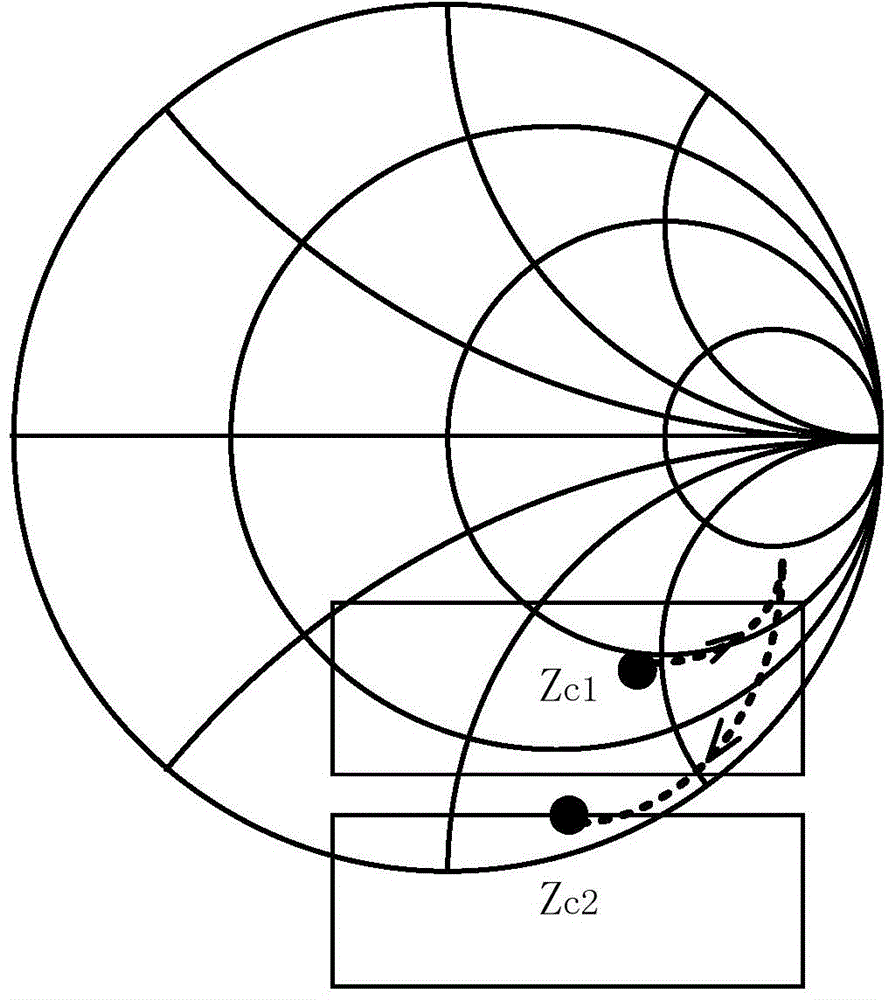
[0029] In addition, in order to maximize the power transmission of the entire UHF RFID electronic tag, it is necessary to achieve a conjugate match between the design impedance of the tag antenna and the tag chip, that is, At this time, the quality factor of the input impedance of the tag and the equivalent i...


PUM


Abstract

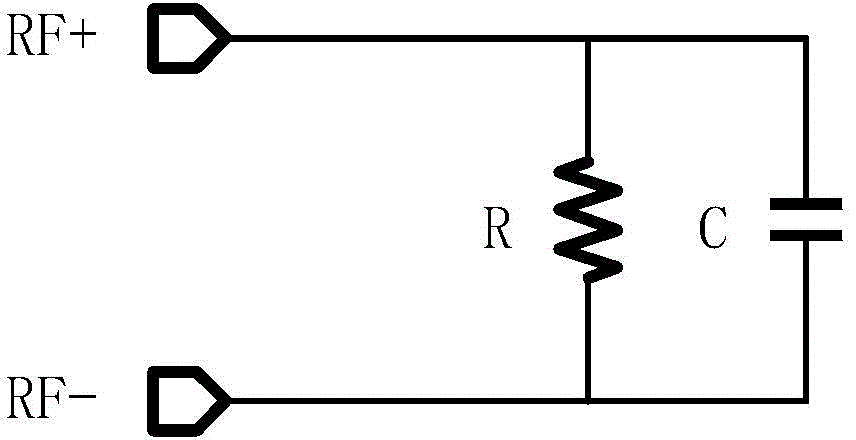
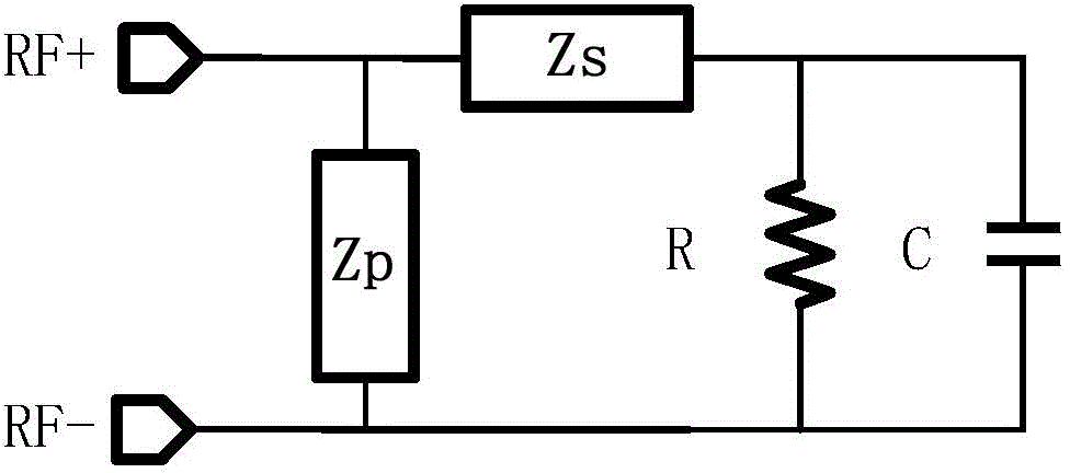
The invention provides an on-chip impedance matching method of an ultrahigh frequency radio frequency identification electronic tag chip. The input impedance of the chip is adjusted through increasing an impedance matching circuit. The method comprises following steps: step 1, constructing the equivalent circuit of input impedance, wherein the equivalent circuit is a two-terminal network formed by connecting a resistor and a capacitor in parallel; and step 2, increasing the L-shaped impedance matching circuit at the output end of the equivalent circuit. Compared with the prior art, in adoption of the on-chip impedance matching method of the ultrahigh frequency radio frequency identification electronic tag chip, the Q value of the ultrahigh frequency radio frequency identification electronic tag chip can be improved in a limited space or under a severer environment condition; and therefore, the normal work of the electronic tag is ensured.

Description

technical field [0001] The invention relates to an impedance matching method, in particular to an on-chip impedance matching method for an ultra-high frequency radio frequency identification electronic tag chip. Background technique [0002] Radio Frequency Identification (RFID) is an automatic identification technology that began to emerge in the 1990s. This technology uses radio frequency signals through spatial coupling, that is, alternating magnetic fields or electromagnetic fields, to achieve non-contact information transmission and realize it with the transmitted information. identify. With its own characteristics, radio frequency identification technology is playing an increasingly important role in the fields of logistics supply chain, food and drug traceability, vehicle traffic management and access control identification. [0003] The radio frequency identification system consists of three parts: electronic tag, reader and host computer, among which the electronic...

Claims


Application Information

Patent Timeline
Patent Type & Authority Applications(China)
IPC IPC(8): G06K19/077G06K19/073
Inventor 管超郝先人
Owner 睿芯联科(北京)电子科技有限公司
Learn More