Automatic control device of choke manifold

A technology for choke manifolds and equipment, applied in wellbore/well components, earthmoving, flushing wellbore, etc., can solve the problem of increasing well kill control time, difficulty in real-time monitoring of casing pressure and riser pressure, unfavorable operation Personnel and managers call, analyze and summarize problems to achieve the effect of increasing accuracy

Inactive Publication Date: 2016-05-11
硕能(上海)自动化科技有限公司
View PDF12 Cites 2 Cited by
  • Summary
  • Abstract
  • Description
  • Claims
  • Application Information

AI Technical Summary

Problems solved by technology

[0004] Defects of the existing technology: the current operation control is entirely based on the actual experience of the operator to manually adjust the opening of the throttle valve, it is difficult to ensure that the entire operation process is a smooth transition
Unstable operation of the throttle valve will lead to large fluctuations in bottomhole pressure. On the one hand, it may lead to well killing failure, blowout or lost circulation again, causing a large amount of economic losses and personnel and property safety problems; on the other hand, it may increase the pressure. The well is difficult, increasing the well killing control time and causing greater economic losses
In particular, the console of the traditional choke manifold only displays the current pressure changes of the casing and standpipe. There is no intuitive knowledge of the hydraulic pump times, and it is difficult to grasp the entire well killing control work from a macro perspective, and it is impossible to achieve efficient and fast well killing control
[0005] In addition, the traditional kill console only displays real-time values ​​of casing pressure and standpipe pressure without storage and recording functions. Operators must record changes in values ​​with pen and paper. Monitoring the casing pressure and riser pressure changes, on the other hand, may be due to the negligence of the operator, misremembering the value, affecting its subsequent judgment, and adversely affecting the well killing work. In addition, this mode is not conducive to the operator and Managers carry out the retrieval, analysis and summary of objective files

Method used


Image

  • Automatic control device of choke manifold
  • Automatic control device of choke manifold

Examples


Embodiment Construction

[0026] The present invention will be described in detail below in conjunction with the accompanying drawings and specific embodiments. This embodiment is carried out on the premise of the technical solution of the present invention, and detailed implementation and specific operation process are given, but the protection scope of the present invention is not limited to the following embodiments.

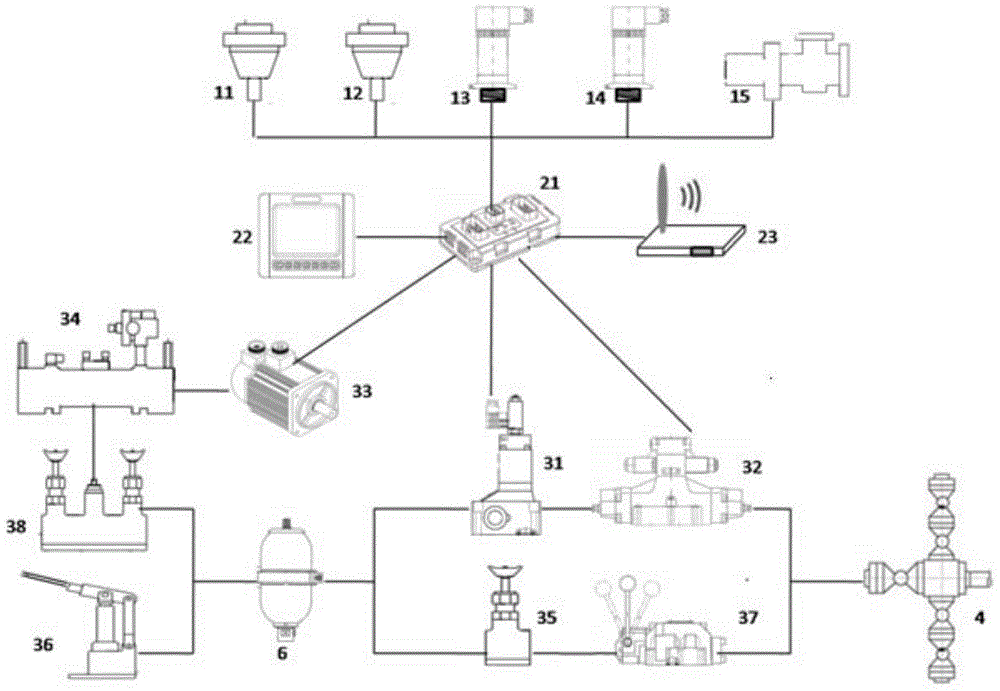
[0027] An automatic control device for a choke manifold, such as figure 1 As shown, the control device includes a sensor assembly 1, a display control assembly 2, and an execution assembly 3. The execution assembly 3 includes a proportional throttle valve 31, an electromagnetic reversing valve 32, a motor 33, a hydraulic pump 34, and a combination valve block 38. The display control The input end of component 2 is connected with sensor component 1, and the output end is respectively connected with proportional throttle valve 31, electromagnetic reversing valve 32 and motor 33, and mot...


PUM


Abstract

The invention relates to an automatic control device of a choke manifold. The control device comprises a sensor assembly, a display control assembly, and an execution assembly. The execution assembly comprises a proportional throttle valve, a magnetic exchange valve, a motor, a hydraulic pump, a combined valve block, and an energy accumulator. The input end of the display control assembly is connected with the sensor assembly, and the output end is connected with the proportional throttle valve, the magnetic exchange valve, and the motor. The motor is connected with the combined valve block through the hydraulic pump. The combined valve block is connected with the energy accumulator. The energy accumulator is connected with the choke manifold through the proportional throttle valve and the magnetic exchange valve in sequence. The display control assembly controls operation of the magnetic exchange valve, the proportional throttle valve, and the motor according to the data acquired by the sensor assembly, so as to realize control on the choke manifold. Compared with the prior art, the device is advantaged by automatic control, and stable control effect.

Description

technical field [0001] The invention relates to an oil drilling equipment, in particular to an automatic control equipment for a throttling manifold. Background technique [0002] The choke manifold control box is a supporting product of the kill choke manifold, which is used in the oil drilling industry. During the drilling process, according to the pressure data of the well killing console, the opening of the choke valve on the choke manifold is manually changed to keep the formation pressure constant during the process of killing the well fluid from the surface of the wellhead, thereby achieving The purpose of scientific and safe well killing. [0003] The current choke manifold control box allows the operator to adjust the opening of the choke valve by looking at the changes in casing pressure and standpipe pressure displayed on the control panel. This adjustment will also display the current choke on the control panel. What is the opening of the valve, such as 3 / 4 or ...

Claims


Application Information

Patent Timeline
Patent Type & Authority Applications(China)
IPC IPC(8): E21B21/08
Inventor 王承震佘益辉钱博宓欣
Owner 硕能(上海)自动化科技有限公司
Why Eureka
Try Eureka