An electromagnetic permanent magnet combined suspension vibration isolation device

A magnetic levitation and permanent magnet technology, applied in building components, earthquake-proof and other directions, can solve unrealistic problems, achieve the effects of levitation stability, elimination of earthquake effects, and low failure rate

Active Publication Date: 2018-04-24
FUZHOU PLANNING DESIGN & RES INST
View PDF11 Cites 0 Cited by
  • Summary
  • Abstract
  • Description
  • Claims
  • Application Information

AI Technical Summary

Problems solved by technology

Although the superconducting technology with a suspension height of 10cm can be used after the superconducting technology is mature, the cost is greatly reduced, and the maintenance is simple and feasible, it is unrealistic to use superconducting technology in civil engineering with a large amount and a wide area at this stage

Method used


Image

  • An electromagnetic permanent magnet combined suspension vibration isolation device
  • An electromagnetic permanent magnet combined suspension vibration isolation device
  • An electromagnetic permanent magnet combined suspension vibration isolation device

Examples


Embodiment Construction

[0022] The present invention will be described in further detail below in conjunction with the accompanying drawings and specific embodiments.

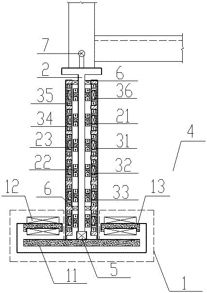
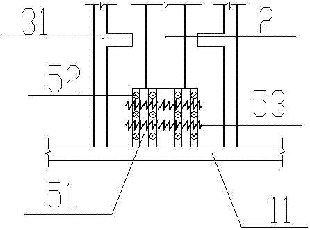
[0023] figure 1 For the consolidation of the magnetic levitation column 4 and the magnetic levitation support 1, the magnetic levitation column 4 is composed of an inner magnetic column 2 and an outer magnetic column 3, the inner magnetic column 2 is inserted into the outer magnetic column 3, and the inner magnetic column 2 rests on the inner magnetic column support 5 Longitudinal sectional view of the electromagnetic permanent magnet combination suspension vibration isolation device.

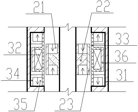
[0024] This hint figure 1 There are 6 groups of 3 magnet groups in the middle and outer magnetic columns, and each group is composed of 2 outer magnetic column permanent magnets 35 and a pair of outer magnetic column electromagnets in the middle. In the present embodiment, the outer magnetic column electromagnets include outer magnetic column coils 32...


PUM


Abstract

The invention provides an electromagnetic permanent magnet combination suspension vibration isolation device. The electromagnetic permanent magnet combination suspension vibration isolation device comprises a magnetic suspension pillar and a vibration isolation support located below the magnetic suspension pillar. The magnetic suspension pillar is composed of an outer magnetic pillar, an inner magnetic pillar and an inner magnetic pillar support. The inner magnetic pillar is sleeved with the outer magnetic pillar without contact, the bottom of the inner magnetic pillar is arranged on the inner magnetic pillar support, and an upper structure is fixed to the top of the inner magnetic pillar. The outer magnetic pillar and the inner magnetic pillar support are fixed to the vibration isolation support. The upper structure is provided with a vibration sensor. The inner magnetic pillar support and the vibration sensor are connected with a control system. The outer magnetic pillar comprises an outer magnetic pillar permanent magnet and an outer magnetic electromagnet. The inner magnetic pillar comprises an inner magnetic pillar permanent magnet. A magnetic force line loop is formed by the inner magnetic pillar and the outer magnetic pillar. When the outer magnetic pillar and the inner magnetic pillar are staggered in the vertical direction, the inner magnetic pillar and the outer magnetic pillar correspondingly produce magnetic force with the direction opposite to the staggering direction. The electromagnetic permanent magnet combination suspension vibration isolation device is good in economical efficiency, the aseismic design standard of a structural body can be greatly lowered under the situation that the earthquake action is basically eliminated, and the expenditure of engineering structure construction is reduced; the property loss and the personnel loss caused by earthquakes can be eliminated, and the mental stress of human facing nature threats is eliminated.

Description

technical field [0001] The invention relates to an engineering structure vibration damping device, in particular to an electromagnetic permanent magnet combined suspension vibration isolation device. Background technique [0002] Magnetic suspension vibration isolation is a new type of active vibration isolation method. It is supported by an actively controlled magnetic field between the vibration source and the structure, so that the vibration source and the structure are completely separated from mechanical contact to achieve the purpose of isolating vibration. Magnetic suspension vibration isolation technology has been successfully used in aerospace, navigation, railway transportation, wind power generation and other fields, but it has not been used in civil engineering. This application is a specific implementation device of the patent "Technical Application of Magnetic Suspension in the Field of Anti-vibration of Engineering Structures" (ZL200910111587.2). [0003] The...

Claims


Application Information

Patent Timeline
Patent Type & Authority Patents(China)
IPC IPC(8): E04B1/98
CPCE04B1/98
Inventor 夏昌刘少克陈宇峰鲁亮龙志强林勇傅大宝林涛黄强
Owner FUZHOU PLANNING DESIGN & RES INST
Why Eureka
Try Eureka