
Ceramic fiber cutting device

A cutting device and ceramic fiber technology, applied in welding equipment, laser welding equipment, metal processing equipment, etc., can solve the problems of low operating accuracy, long optical path, increased machine weight, etc., achieve high positioning accuracy, ensure cutting accuracy, The effect of reducing the span

Inactive Publication Date: 2016-05-11
天津市广盛源新型建材科技有限公司
View PDF0 Cites 2 Cited by
  • Summary
  • Abstract
  • Description
  • Claims
  • Application Information

AI Technical Summary

Problems solved by technology

[0004] The present invention provides a ceramic fiber cutting device to solve the problems of too long optical path, increased machine weight, and low operating precision in the above-mentioned background technology

Method used


Image

  • Ceramic fiber cutting device
  • Ceramic fiber cutting device
  • Ceramic fiber cutting device

Examples


Embodiment

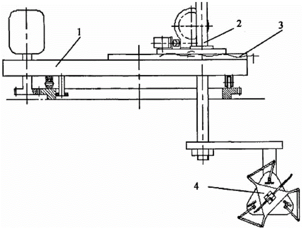
[0016] Embodiment: A ceramic fiber cutting device of the present invention consists of a horizontal rotation mechanism 1, a vertical lifting mechanism 2, a radial adjustment mechanism 3 and a swing mechanism 4, and a radial adjustment mechanism 3 is installed on one side of the horizontal rotation mechanism 1, and a vertical lifting mechanism 2 is installed vertically through the radial adjustment mechanism 3, and the lower end of the vertical lifting mechanism 2 is connected to the swing mechanism 4.

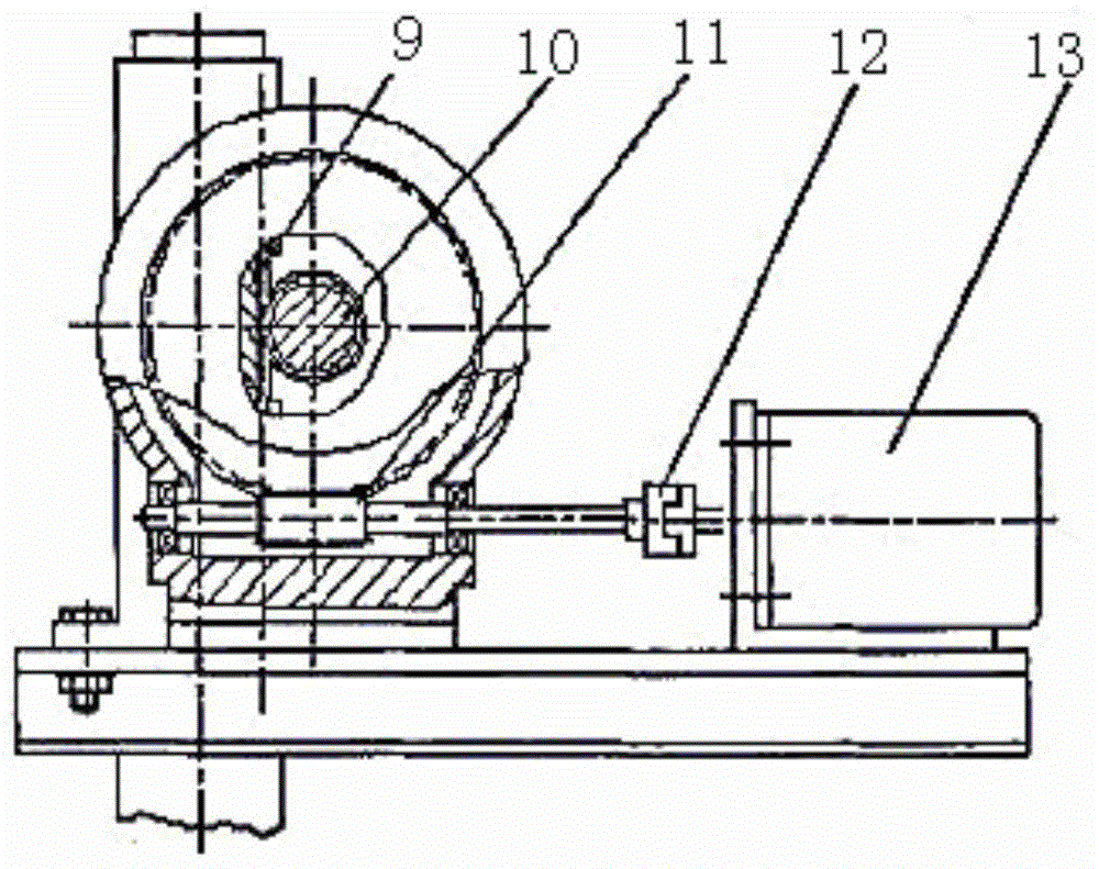
[0017] The horizontal rotation mechanism 1 includes a stepping motor 5 and a slewing bridge 6, the stepping motor 5 is installed on one end of the slewing bridge 6, the small ring gear 8 is connected to the stepping motor 5, and the large ring gear 7 mounted on the base is connected to the pinion 8 . The slewing bridge composed of two rails is placed on the large ring gear, and four rolling bearings are fixed under the slewing bridge to form a four-point support with the large ...


PUM


Abstract

The invention belongs to the field of mechanical equipment, and particularly relates to a ceramic fiber cutting device. The ceramic fiber cutting device is composed of a horizontal rotation mechanism (1), a vertical lifting mechanism (2), a radial adjustment mechanism (3) and a swing mechanism (4); and the radial adjustment mechanism (3) is installed on one side of the horizontal rotation mechanism (1), the vertical lifting mechanism (2) is vertically installed on the radial adjustment mechanism (3) in a penetrating manner, and the lower end of the vertical lifting mechanism (2) is connected with the swing mechanism (4). The structure manner that a circular orbit rotary bridge is combined with a cantilever is adopted in the ceramic fiber cutting device so that the span of a cutting machine can be effectively reduced through the structure, the overall size can be decreased, and meanwhile the cutting accuracy can be guaranteed. The overall weight of the rotation mechanism, a radial feeding mechanism, a cantilever support structure and the swing mechanism is supported by outer rings of four rolling bearings, when the rotary bridge rotates, the outer rings of the bearings move on the end plane of a large gear ring, the friction coefficient is small, dynamic coefficients are approximate to static friction coefficients, the crawl phenomenon is avoided, motion is light and flexible, and the positioning accuracy is high.

Description

technical field [0001] The invention belongs to the technical field of mechanical equipment, in particular to a cutting machine for processing ceramic fiber boards. Background technique [0002] After more than 20 years of development, my country's CNC cutting technology has developed from a single CNC flame cutting technology to a modern cutting technology with multiple energy sources and multiple process methods such as CNC plasma arc cutting, laser cutting, and water jet cutting. CNC flame cutting is the earliest CNC cutting mechanism in China. With the rapid development of my country's economy, CNC cutting technology has been widely used in domestic shipbuilding, pressure vessels, engineering machinery, power station equipment, bridges and steel structures, and has completely changed The low efficiency of manual and semi-automatic cutting in the past. It fundamentally alleviates the huge pressure of the sharp increase in the cutting volume of steel plates and other metal...

Claims


Application Information

Patent Timeline
Patent Type & Authority Applications(China)
IPC IPC(8): B23K26/70
Inventor 王禄
Owner 天津市广盛源新型建材科技有限公司
Learn More