
Driving method for led driver

An LED driver and driving method technology, applied in lighting devices, light sources, electrical components, etc., can solve the problems of DC bus overvoltage, damage to the system, system damage, etc., to achieve the effect of safe startup and avoid system abnormalities

Active Publication Date: 2017-05-03
JIANGSU LIGEN ELECTRIC POWER ELECTRONICS TECH CO LTD
View PDF3 Cites 0 Cited by
  • Summary
  • Abstract
  • Description
  • Claims
  • Application Information

AI Technical Summary

Problems solved by technology

[0002] In recent years, low-voltage LED lamps have begun to replace halogen lamps. Due to their advantages in light efficiency and service life, they have received widespread attention. However, there is a problem that has not been well solved in the application: electronic transformers.
Because it is originally designed to power purely resistive loads such as halogen lamps, and requires a large current to trigger conduction, in addition, electronic transformers are prone to accidental shutdown when they have capacitive or non-linear loads
[0003] After research by the applicant, it was found that the prior art scheme adopts a fixed-mode soft-start pulse sequence for starting the low-voltage LED. The main switching tube may switch with a large duty cycle. At this time, if the external AC power is switched on suddenly, a large inrush current and DC bus overvoltage will be generated, which will bring excessive stress to the components in the system and damage the system.
In the power-on process of the traditional low-voltage LED drive system, due to the lack of detection of AC input, a large voltage overvoltage is observed, which will cause system damage in severe cases

Method used


Image

  • Driving method for led driver
  • Driving method for led driver
  • Driving method for led driver

Examples


Embodiment Construction

[0029] In order to solve the above problems, the applicant has carried out in-depth research, the research process is as described in the background technology, and will not be described here. Based on the above research, the applicant proposes the following solutions. The method comprises the steps of:

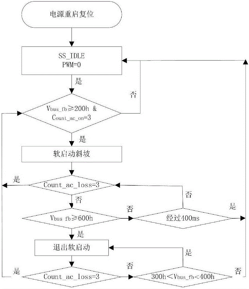
[0030] Detect whether there is an AC input signal, and if there is an AC input signal, start the ramp up of the PWM;

[0031] Detect whether the bus voltage feedback signal is greater than a predetermined value, if greater than the predetermined value, then end the start-up process.

[0032] The above method can effectively solve the problems existing in the prior art. When there is no AC input signal, the soft start program does not work, so the situation mentioned in the background art does not occur. It is safer to start and can avoid abnormal situations.

[0033] In a further embodiment, whether there is an AC input signal is judged based on the number of rising edges ...


PUM


Abstract

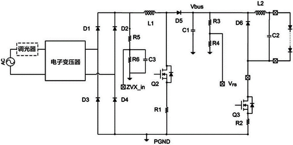
The invention discloses an AC input detection and starting circuit of an LED driver and an LED driving method. The AC input detection and starting circuit of the LED driver includes a filter and an intermediate voltage feedback network; wherein the filter includes a fifth resistor , the sixth resistor and the third capacitor, one end of the fifth resistor is connected to the output end of the rectifier bridge, the other end is connected to the sixth resistor and one end of the third capacitor, the other end of the sixth resistor is connected to the other end of the third capacitor to ground ; The rectifier bridge filter output detection terminal is connected between the fifth resistor and the sixth resistor; the intermediate stage voltage feedback network includes the third resistor and the fourth resistor, one end of the third resistor is connected to the cathode of the fifth diode, and the fourth One end of the resistor is grounded, and the bus voltage detection end is connected between the third resistor and the fourth resistor. The implementation of the invention can make the start-up of the transformer safer, without flickering and voltage overshoot, and avoids system abnormalities related to overvoltage during the start-up process.

Description

technical field [0001] The invention belongs to the field of LEDs, in particular to an AC input detection and starting circuit of an LED driver and an LED driving method. Background technique [0002] In recent years, low-voltage LED lamps have begun to replace halogen lamps. Due to their advantages in light efficiency and service life, they have received widespread attention. However, there is a problem that has not been well solved in the application: electronic transformers. The electronic transformer is essentially a self-oscillating resonant transformer, which can convert power frequency alternating current into 12V voltage available for low-voltage halogen lamps. Because it was originally designed to power purely resistive loads such as halogen lamps, and requires a large current to trigger conduction, in addition, electronic transformers are prone to accidental shutdown when they have capacitive or non-linear loads. [0003] After research by the applicant, it was fo...

Claims


Application Information

Patent Timeline
Patent Type & Authority Patents(China)
IPC IPC(8): H05B33/08H05B44/00
CPCH05B45/50H05B45/37
Inventor 钱昶
Owner JIANGSU LIGEN ELECTRIC POWER ELECTRONICS TECH CO LTD
Learn More