A DC blocking circuit and a switching circuit

A DC blocking circuit and circuit technology, applied in the field of DC blocking circuits and switching circuits, can solve the problems of increased cost and larger circuit area, and achieve the effect of reducing the area, reducing the degree of degradation, and reducing the area of ​​the capacitor

Active Publication Date: 2019-03-19
SHANGHAI HUAHONG GRACE SEMICON MFG CORP
View PDF6 Cites 0 Cited by
  • Summary
  • Abstract
  • Description
  • Claims
  • Application Information

AI Technical Summary

Problems solved by technology

In the prior art, in order to avoid a greater degree of insertion loss, it is necessary to increase the capacitance value by increasing the area of ​​the DC blocking capacitor, resulting in larger circuit area and increased cost

Method used


Image

  • A DC blocking circuit and a switching circuit
  • A DC blocking circuit and a switching circuit
  • A DC blocking circuit and a switching circuit

Examples


Embodiment Construction

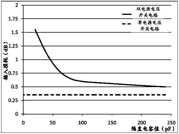
[0029] It can be seen from the background art that the degradation degree of insertion loss in the single power supply voltage switching circuit of the prior art is relatively serious, and the circuit area is relatively large.

[0030] The inventor of the present invention has studied the prior art single power supply voltage switching circuit, and found that the DC blocking capacitor will cause a large degree of insertion loss degradation. In order to reduce the degradation of insertion loss, it is necessary to increase the DC blocking capacitor. area, resulting in an increase in circuit area.

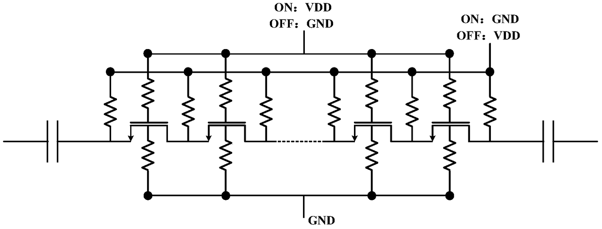
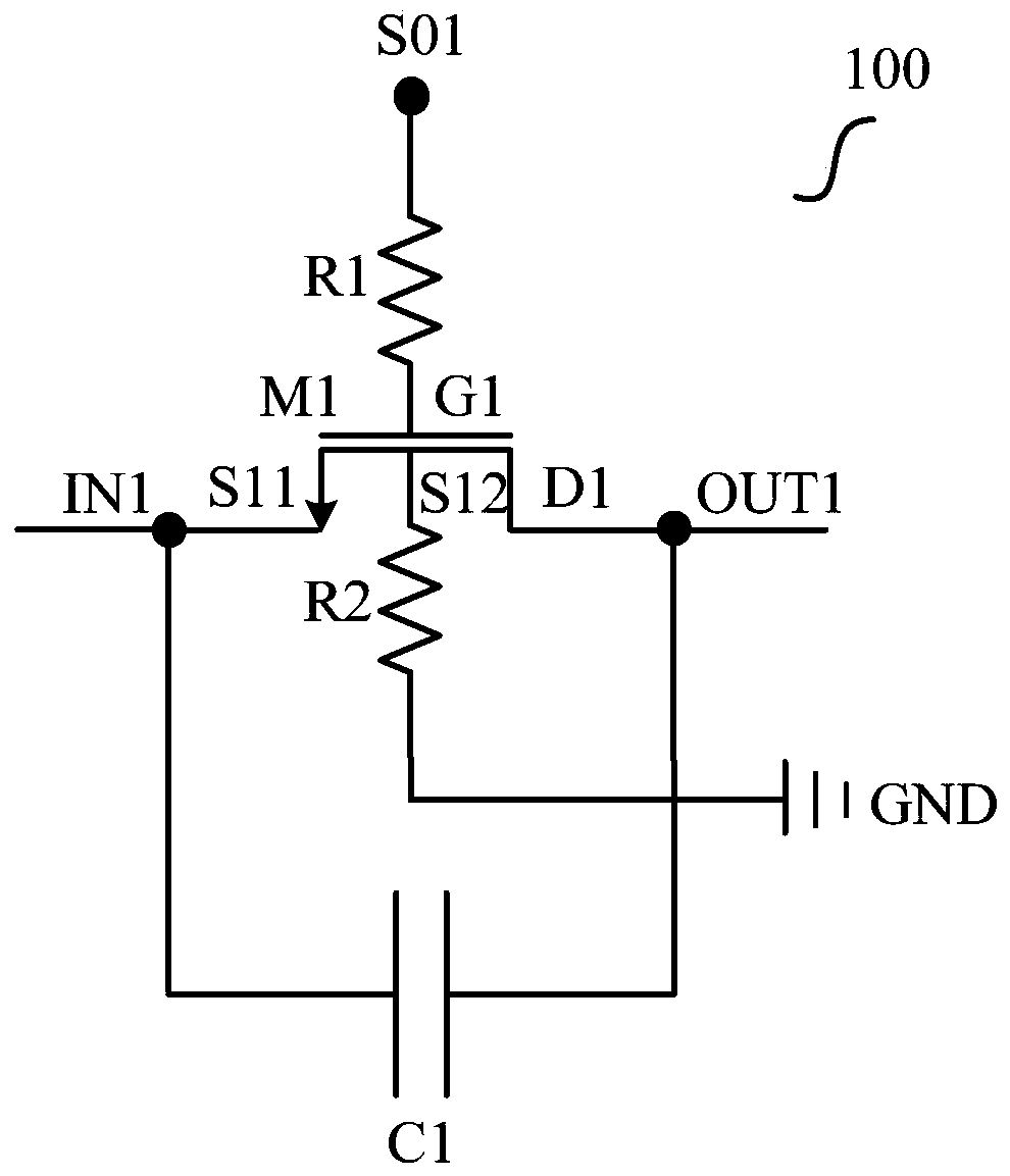
[0031] The embodiment of the present invention proposes a DC blocking circuit, which uses a parallel connection of a MOS tube and a capacitor to block the DC bias, and reduces the capacitance value and area of ​​the DC blocking capacitor compared with the solution of only using the capacitor.

[0032] In order to make the purpose, features and effects of the present invention more obv...


PUM


Abstract

The invention relates to a direct current blocking circuit and a switching circuit; the direct current blocking circuit is used for blocking a direct current bias; the direct current blocking circuit comprises a first MOS (Metal Oxide Semiconductor) tube, a first resistor, a second resistor and a first capacitor, wherein the first MOS tube, the first resistor and the second resistor are in serial connection; the first capacitor is in parallel connection with the first MOS tube; the grid electrode of the first MOS tube is coupled to the first end of the first resistor, the source electrode of the first MOS tube is coupled to the input end of the direct current blocking circuit and the first end of the first capacitor, and the drain electrode of the first MOS tube and the second end of the first capacitor are coupled to the output end of the direct current blocking circuit; the first end of the second resistor is coupled to the substrate end of the first MOS tube, and the second end of the second resistor is grounded; the second end of the first resistor is coupled to a first control signal; and when the first control signal is a power signal, the first MOS tube is in a conducting state. According to the direct current blocking circuit and the switching circuit disclosed by the invention, on the basis of keeping no degradation of the high-power linearity and the simple structure, the circuit area is decreased, and the degradation degree of insertion loss is reduced.

Description

technical field [0001] The invention relates to the technical field of integrated circuits, in particular to a DC blocking circuit and a switching circuit. Background technique [0002] Traditional switching circuits, such as antenna switching circuits, use positive and negative dual power supply voltages to drive the control switches to obtain better high-power linearity. However, the circuit structure for generating the negative power supply voltage is relatively complex, consumes a large amount of power, and at the same time generates noise and other interferences that affect the performance of the switch. [0003] With the development of circuit technology, the switching circuit can only use the positive power supply voltage to drive the control switch. figure 1 A schematic structural diagram of a switch circuit using only a positive power supply voltage in the prior art is shown. Its driving method is similar to that of a switching circuit using positive and negative ...

Claims


Application Information

Patent Timeline
Patent Type & Authority Patents(China)
IPC IPC(8): H03K17/687
CPCH03K17/687
Inventor 戴若凡
Owner SHANGHAI HUAHONG GRACE SEMICON MFG CORP
Why Eureka
Try Eureka