
Micro-earthquake epicenter positioning method calculated based on multilevel multi-scale grid similarity coefficient

A similarity coefficient and source location technology, applied in seismic signal processing and other directions, can solve problems such as the inability to meet the accuracy and real-time performance at the same time, the inability to improve computational efficiency and computational accuracy at the same time, and the limited application range, so as to avoid excessive positioning accuracy. The effect of low and high precision microseismic source location

Inactive Publication Date: 2016-05-04
CHINA UNIV OF MINING & TECH (BEIJING)
View PDF3 Cites 13 Cited by
  • Summary
  • Abstract
  • Description
  • Claims
  • Application Information

AI Technical Summary

Problems solved by technology

[0007] The present invention aims to solve the problem that the calculation efficiency and calculation accuracy of the traditional seismic source location algorithm based on similarity coefficient calculation cannot be improved at the same time, and the accuracy and real-time performance cannot be satisfied at the same time when applied to microseismic source location, resulting in limited application range. Scale grid division, compared with the positioning method of calculating the similarity coefficient in the traditional uniform grid division, improves the calculation efficiency and calculation accuracy of the positioning method at the same time, meets the real-time monitoring of microseismic monitoring, and realizes the precise positioning of the source

Method used


Image

  • Micro-earthquake epicenter positioning method calculated based on multilevel multi-scale grid similarity coefficient
  • Micro-earthquake epicenter positioning method calculated based on multilevel multi-scale grid similarity coefficient
  • Micro-earthquake epicenter positioning method calculated based on multilevel multi-scale grid similarity coefficient

Examples


Embodiment Construction

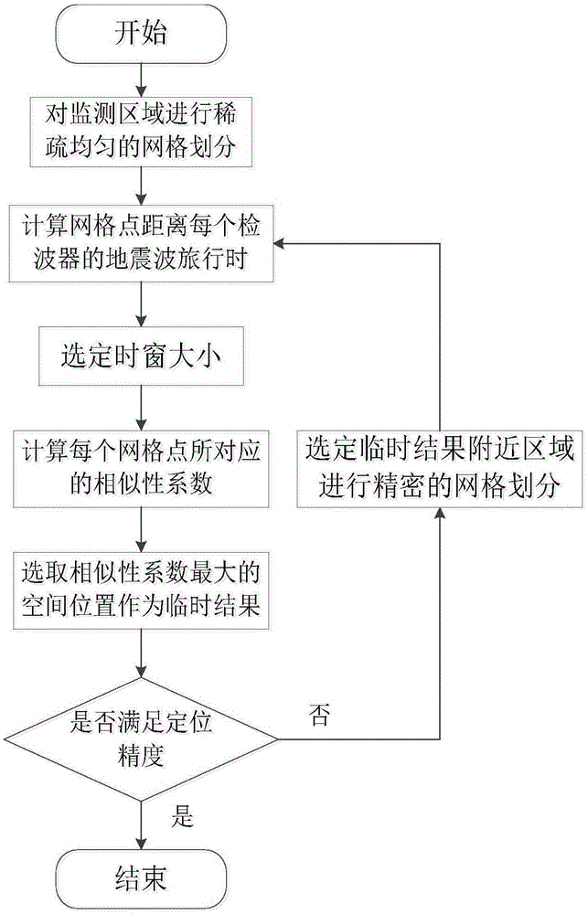
[0029] The basic implementation steps of the microseismic source location method based on multi-level grid division and similarity coefficient are as follows:

[0030]Step 1: Uniformly discretize the microseismic monitoring area into a grid model of i row x j column, and store the coordinate position of the corresponding grid segmentation point in a two-dimensional array L of i row x j column 0 , numbering row by row from the origin to create a two-dimensional array L of i row x j column 1 , the array L 1 The value of the element in is the average propagation velocity corresponding to the physical position of the grid space, and the numbering sequence is the same as that of L 0 .

[0031] Step 2: According to the array L 1 Calculate the travel time of seismic waves from each grid position in the grid model of i row x j column to each geophone, and store it in the three-dimensional array L of i row x j column x m channel 3 , where m channels represent the number of detector...


PUM


Abstract

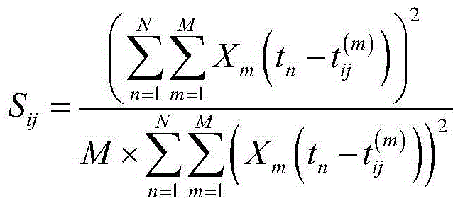
The invention discloses a micro-earthquake epicenter positioning method, belongs to the field of earth physics inversion algorithms. The positioning method comprises the following steps that a monitoring area is divided into uniform grids; the earthquake amplitude similarity coefficient corresponding to each grid division point is calculated; the grid position corresponding to the maximal similarity coefficient is selected as an epicenter positioning result; and the grid corresponding to the positioning result is further divided into grids uniformly, the similarity coefficients are calculated, and the grid position corresponding to the maximal similarity coefficient to update the epicenter positioning result till the positioning precision satisfies requirements. Compared with a traditional similarity coefficient positioning method, multilevel multi-scale grid division is carried out on the monitoring area, the disadvantage that the calculation time is too long caused by wholly dense grid division of the monitoring area is overcome, and the defect that the positioning precision is too low due to wholly sparse grid division of the monitoring area is also overcome.

Description

technical field [0001] The invention relates to a microseismic positioning and inversion method based on multi-level and multi-scale grid division using similarity coefficients, and relates to the technical field of geophysical detection, in particular to a microseismic monitoring and positioning inversion method. Background technique [0002] As the precursor of large-scale dynamic disasters in the underground medium, the micro-vibration in the ground can effectively monitor the rupture of the underground medium and provide information for the prevention of large-scale dynamic disasters for the real-time positioning of the micro-seismic source. In the microseismic monitoring work, how to accurately locate the microseismic source is the key to the success of the monitoring work. Microseismic monitoring has been widely used in the engineering field because of its ability to monitor the degree of medium rupture in real time. In the coal mine system, microseismic monitoring is ...

Claims


Application Information

Patent Timeline
IPC IPC(8): G01V1/28
CPCG01V1/28
Inventor 郑晶姜天琪彭苏萍陆继任
Owner CHINA UNIV OF MINING & TECH (BEIJING)
Learn More