
Positioning device and positioning method of partial discharge source of electrical device

A technology of electrical equipment and positioning devices, which is applied in the direction of measuring devices, measuring electricity, and measuring electrical variables, etc., can solve problems such as large noise influence, low signal-to-noise ratio, and demanding manufacturing process requirements, and achieve high signal-to-noise ratio advantages and high The effect of resolving power and high sensitivity

Active Publication Date: 2016-05-04
NORTH CHINA ELECTRIC POWER UNIV (BAODING)
View PDF6 Cites 10 Cited by
  • Summary
  • Abstract
  • Description
  • Claims
  • Application Information

AI Technical Summary

Problems solved by technology

The scalar sound pressure sensor has very low sensitivity, no azimuth information of the sound field, and the target cannot be determined. In the sound intensity processing, the isotropic noise cannot cancel each other out, and the signal-to-noise ratio is low; it is also used in the detection of partial discharge in the insulating oil of electrical equipment Ordinary ultrasonic positioning devices, due to more interference and greater noise impact, sound waves may be reflected, resulting in the detection of multiple partial discharge sources that are inconsistent with the actual situation, resulting in positioning failure
[0005] The ultrasonic vector array element used in the partial discharge ultrasonic vector array positioning device of electrical equipment in the prior art includes three piezoelectric velocity sensors and a wireless data acquisition module, which can realize the accurate positioning of the partial discharge position of electrical equipment; The corresponding effect of high-frequency signals is poor, and its center of gravity must be located on the center of the ball during production, coupled with the small size and high density requirements, resulting in demanding manufacturing processes and inconvenient mass production

Method used


Image

  • Positioning device and positioning method of partial discharge source of electrical device
  • Positioning device and positioning method of partial discharge source of electrical device
  • Positioning device and positioning method of partial discharge source of electrical device

Examples


Embodiment Construction

[0035] The present invention will be further described in detail below in conjunction with the accompanying drawings and specific embodiments.

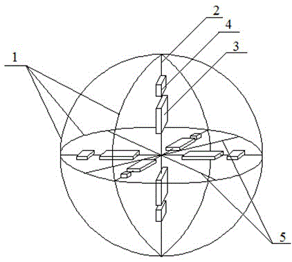
[0036] The invention includes a differential pressure vector sensor, a high-frequency carrier communication module and an analyzing device. The differential pressure vector sensor is set in the insulating oil of electrical equipment to collect discharge information; the high-frequency carrier communication module is used to send the information transmitted by the differential pressure vector sensor to the analysis device; the analysis device is set in the control room for The information collected by the differential pressure vector sensor is analyzed to obtain the specific location of the partial discharge source.

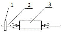
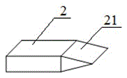
[0037] Differential pressure vector sensor, including a spherical structure, six double-stacked curved piezoelectric ceramic sensors 3, six data acquisition modules 4, and connecting rods for fixing the double-stacked cur...


PUM


Abstract

The present invention discloses a positioning device and positioning method of a partial discharge source of an electrical device. The positioning device comprises a pressure differential vector sensor, a high-frequency carrier communication module and an analysis device. The pressure differential vector sensor is arranged in the insulating oil of the electrical device and configured to collect discharge information; the high-frequency carrier communication module is configured to send the transmission information of the pressure differential vector sensor to the analysis device; and the analysis device is arranged in a control chamber and configured to perform analysis of information collected by the pressure differential vector sensor to obtain the concrete position of the partial discharge source. The positioning device and positioning method of a partial discharge source of an electrical device are used for positioning the partial discharge source in the insulating oil of the electrical device, with simple structure, convenient usage and accurate positioning.

Description

technical field [0001] The invention relates to the technical field of electrical equipment detection, in particular to a device and method for detecting partial discharge positions in electrical equipment insulating oil. Background technique [0002] With the development of our country's economy, the requirements for the reliability of the power system are getting higher and higher. As the hub of the power system, the reliability of the operation of electrical equipment is directly related to the safety and stability of the power system. During the long-term operation of electrical equipment, due to problems such as insulation aging, overvoltage, or uneven structure of the insulation layer of electrical equipment, it is easy to cause local insulation performance to decline. These insulation-weakened parts will take the lead in various types of discharges, resulting in insulation. Further damage to the electrical equipment causes various short-circuit faults to occur inside ...

Claims


Application Information

Patent Timeline
IPC IPC(8): G01R31/12
CPCG01R31/1281
Inventor 谢庆王涛刘绪英刘丹陶珺函赵蓓蓓徐玉琴
Owner NORTH CHINA ELECTRIC POWER UNIV (BAODING)
Learn More