
LED ceiling lamp with light guide plate

An LED ceiling lamp, light guide plate technology, applied in optics, light guides, light sources, etc., can solve the problems of high cost of lens molds, large differences in the light output effect on the surface of the mask, and high manufacturing costs, to simplify the production and assembly process, optimize the cost, Assembly of simple effects

Inactive Publication Date: 2016-05-04
SIMON ELECTRIC CHINA
View PDF5 Cites 9 Cited by
  • Summary
  • Abstract
  • Description
  • Claims
  • Application Information

AI Technical Summary

Problems solved by technology

[0002] At present, the existing LED ceiling lamps basically adopt the arrangement of low-power lamp beads to fill the chassis, or adopt the method of medium-power lamps and lenses to achieve uniform illumination on the surface of the mask. Both of these methods have high manufacturing costs, high lens mold costs, and The problem of the large difference in the light output effect of different mask surfaces

Method used


Image

  • LED ceiling lamp with light guide plate
  • LED ceiling lamp with light guide plate
  • LED ceiling lamp with light guide plate

Examples


Embodiment Construction

[0038] In order to describe the technical content of the present invention more clearly, further description will be given below in conjunction with specific embodiments.

[0039] In order to achieve the above object, the present invention adopts the following technical solutions:

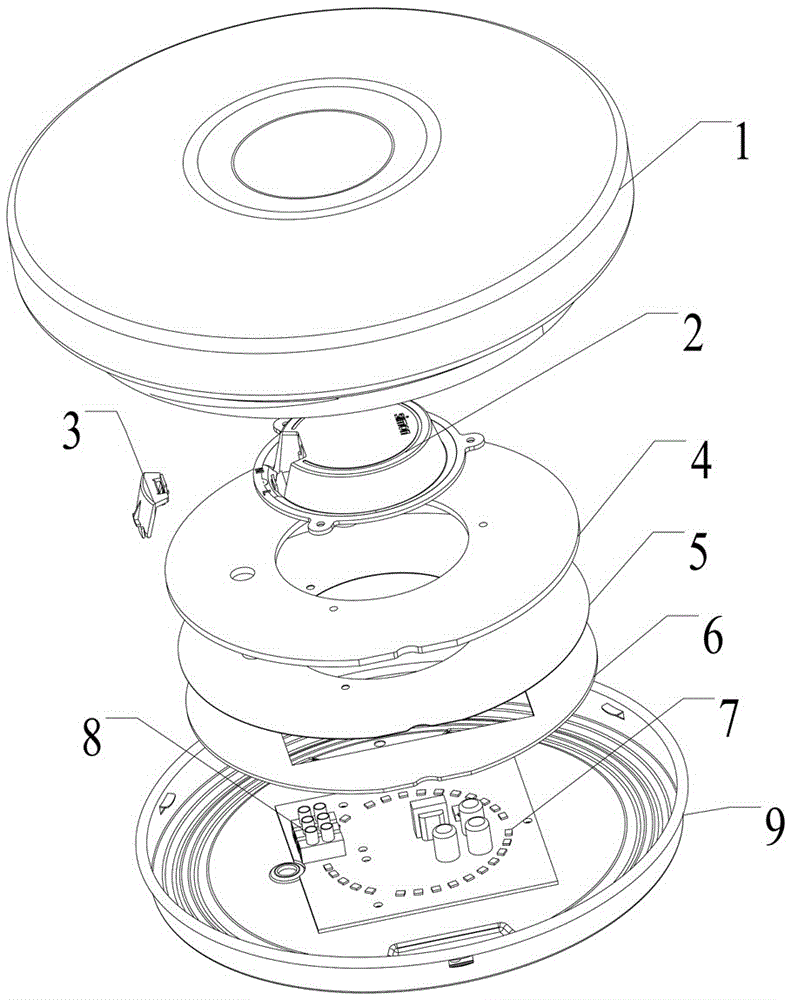
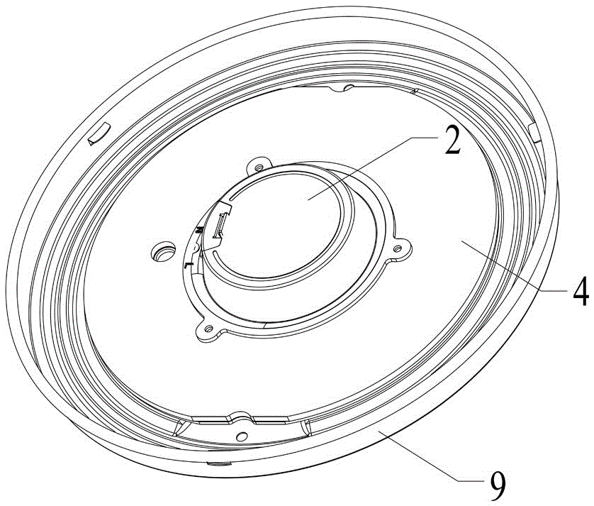
[0040] The light emitting mode of the point light source of the light source is designed as the light emitting mode of the surface light source, and the light emitting mode is converted by using the microstructure light guide plate, which simplifies the processing process, realizes cost optimization, simple assembly, and one model of light source can adapt to the light emitting effect of masks with different appearances. Has the following composition:

[0041] 1. The light source part of the lamp: the LED light source 10 and the power supply are concentrated on one PCB board, and the full patch process is adopted to avoid the arrangement of welding wires during the assembly process. The terminal 8,...


PUM


Abstract

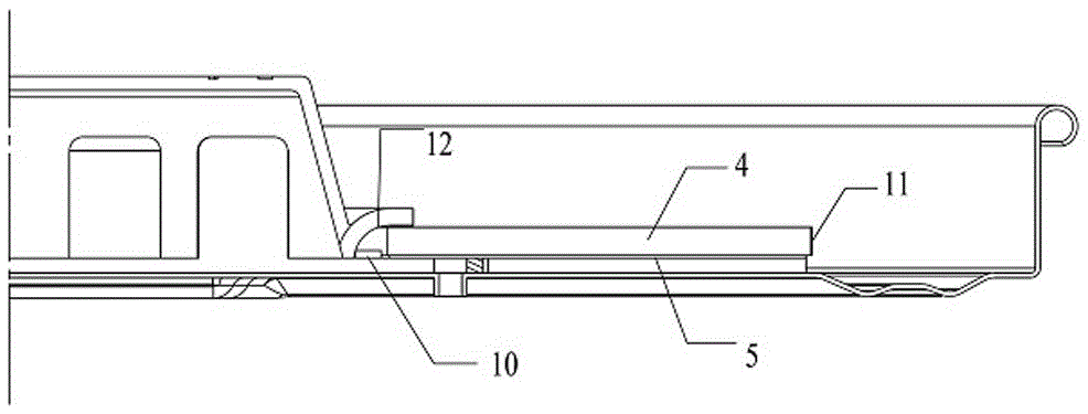
The invention relates to an LED ceiling lamp with a light guide plate. The LED ceiling lamp comprises a power shell, a power box cover, the light guide plate, a light and power source panel, an LED light source, a reflecting film and wiring terminals. The light guide plate is annular. The annular reflecting film is arranged on the lower surface of the light guide plate. The upper surface of the light guide plate is of a prism structure, and a concave point is formed in the lower surface of the light guide plate. The light and power source panel is arranged below the reflecting film and provided with the wiring terminals. The power shell and the power box cover are sequentially arranged above the light guide plate. The LED light source is arranged below the light guide plate. According to the LED ceiling lamp with the light guide plate of the structure, the point light source light emitting mode of a light source part is designed to be an area light source light emitting mode; the producing and assembling process is simplified; the light emitting effects that the cost is optimized, assembling is easy, and light source assemblies of one type can adapt to covers of different appearances are achieved; and the wider application range is achieved.

Description

technical field [0001] The invention relates to the technical field of lamps, in particular to the technical field of ceiling lamps, in particular to an LED ceiling lamp with a light guide plate. Background technique [0002] At present, the existing LED ceiling lamps basically adopt the arrangement of low-power lamp beads to fill the chassis, or adopt the method of medium-power lamps and lenses to achieve uniform illumination on the surface of the mask. Both of these methods have high manufacturing costs, high lens mold costs, and The problem of the large difference in the light output effect of different mask surfaces. Contents of the invention [0003] The purpose of the present invention is to overcome the above-mentioned shortcomings of the prior art, and to provide an LED ceiling lamp with a light guide plate that can meet the requirements of use, has simple manufacturing process, controllable manufacturing, and low cost. [0004] In order to achieve the above objec...

Claims


Application Information

Patent Timeline
Patent Type & Authority Applications(China)
IPC IPC(8): F21S8/04F21V23/00F21V8/00F21V15/01F21V17/10F21Y115/10
CPCF21S8/04F21V15/01F21V17/10F21V23/005
Inventor 谭桂琴王强朱红旗
Owner SIMON ELECTRIC CHINA
Learn More