
Electric control system two-pin electromagnetic valve for automobile engine

A technology of automobile engine and electronic control system, applied in the direction of engine components, machine/engine, electronic control, etc., can solve the problem that the soft contact between the valve pin and the driven slider cannot be guaranteed, and the action of the valve pin of the electromagnetic drive cannot be determined. In order to achieve the effect of highlighting the substantive features, reducing the impact and improving the response speed

Inactive Publication Date: 2016-05-04
CHENGDU FULIN PRECISION AUTOMOTIVE COMPONENTS CO LTD
View PDF7 Cites 11 Cited by
  • Summary
  • Abstract
  • Description
  • Claims
  • Application Information

AI Technical Summary

Problems solved by technology

[0004] 1. It is impossible to determine the action of the valve pin of the electromagnetic driver, so it is impossible to determine whether the valve pin is working properly;
[0005] 2. The electromagnetic driver of the existing electronic control system cannot guarantee the soft contact between the valve pin and the combined groove of the driven slider;
[0006] 3. The electromagnetic driver of the existing electronic control system has no lubrication protection for the valve pin structure of the electromagnetic driver

Method used


Image

  • Electric control system two-pin electromagnetic valve for automobile engine
  • Electric control system two-pin electromagnetic valve for automobile engine
  • Electric control system two-pin electromagnetic valve for automobile engine

Examples


Embodiment Construction

[0036] In order to make the object, technical solution and advantages of the present invention clearer, the present invention will be described in detail below in conjunction with the accompanying drawings and specific embodiments. It should be understood that the specific embodiments described here are only used to explain the present invention, not to limit the present invention.

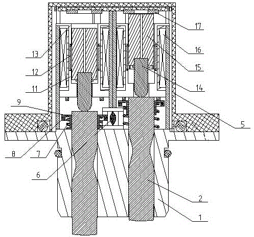
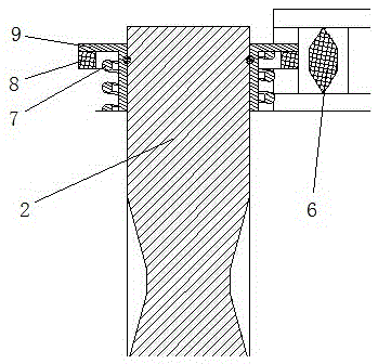
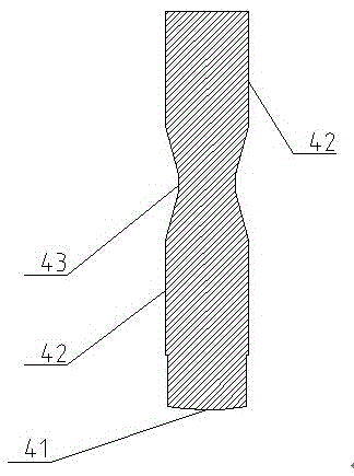
[0037] It can be seen from the accompanying drawings that this solution includes a pin sleeve installed on the valve casing, and a valve pin is arranged inside the pin sleeve; an electromagnetic driver is arranged inside the valve casing; the electromagnetic driver includes a front yoke sleeve, a rear yoke sleeve, and a connecting The guide sleeve, magnetic core and push rod of the yoke sleeve; the guide sleeve and the front and rear yoke sleeves are wrapped with electromagnetic solenoids; the guide sleeve is provided with a magnetic core; the front part of the magnetic core is in contact with the ...


PUM


Abstract

The invention provides an electric control system two-pin electromagnetic valve for an automobile engine. According to the scheme, the electric control system two-pin electromagnetic valve comprises a pin sleeve installed on a valve shell, and valve pins are arranged in the pin sleeve; electromagnetic actuators are arranged in the valve shell; each electromagnetic actuator comprises a front yoke sleeve, a rear yoke sleeve, a guide sleeve for connecting the front yoke sleeve with the rear yoke sleeve, a magnetic core and a push rod, wherein the guide sleeve and the front and rear yoke sleeves are wrapped by an electromagnetic solenoid, the magnetic core is arranged in the guide sleeve, the front portion of the magnetic core makes contact with the push rod, the push rod is arranged in the front yoke sleeve, the push rod makes contact with the corresponding valve pin, and a magnetic core reset mechanism is arranged between the rear portion of the magnetic core and the valve shell. By means of the scheme, magnetism can be ensured, it can be ensured that the valve pins can make soft contact with the valve shell and the pin sleeve when moving, the valve pins can be effectively lubricated, and meanwhile whether the valve pins act in place or not can be accurately detected.

Description

technical field [0001] The invention relates to an electromagnetic drive valve, in particular to a double-pin electromagnetic valve used in an electric control system of an automobile engine. Background technique [0002] In previously known electromagnetic devices for adjusting the amount of valve lift of an engine, it is known to vary the position of a slider which is rotatable integrally with the shaft and which moves relative to the shaft along its axial direction. The electromagnetic driver is the driving mechanism that drives the slider to move, and it controls the axial movement of the drive relative to the shaft according to the signal sent by the engine controller. In order to realize the movement of the axial slider, so as to realize the purpose of adjusting the valve lift. [0003] However, the existing electric control system electromagnetic driver has the following defects: [0004] 1. It is impossible to determine the action of the valve pin of the electromag...

Claims


Application Information

Patent Timeline
Patent Type & Authority Applications(China)
IPC IPC(8): F16K31/06F01L13/00
CPCF16K31/0644F01L13/00F01L2201/00
Inventor 阳宇张金伟胡荣王哲
Owner CHENGDU FULIN PRECISION AUTOMOTIVE COMPONENTS CO LTD
Learn More