
Concrete bridge reinforcing method and structure

A technology for strengthening structures and concrete, applied in the direction of bridge reinforcement, bridges, bridge materials, etc., can solve the problems of increasing the burden of piers and foundations, reducing the principal stress of the anchorage area, and the self-heavy weight of the reinforcement system, so as to improve the crack resistance and bearing capacity. , High flexural reinforcement efficiency, the effect of ensuring the effect of crack resistance reinforcement

Inactive Publication Date: 2016-05-04
CHINA SHENHUA ENERGY CO LTD +2
View PDF6 Cites 8 Cited by
  • Summary
  • Abstract
  • Description
  • Claims
  • Application Information

AI Technical Summary

Problems solved by technology

[0004] However, in the existing external prestressing beam reinforcement method, the anchor beam as a whole bears the prestress generated by all the prestressing beams, resulting in the prestress usually concentrated on the same section and the same point, and the anchoring force is relatively concentrated, which is not conducive to stress diffusion. The relative concentration of the anchoring force inevitably requires the anchoring beam and the steering beam to have a larger size. At the same time, it is necessary to lay and stretch a certain number of transverse prestressed beams in the beam to reduce the principal stress in the anchorage area.
Due to the large self-weight of the reinforcement system (the weight of the additional structure accounts for about 8% to 10% of the original structure), the reinforcement efficiency of the reinforcement system to the original bridge structure is correspondingly reduced. In addition, the self-weight of the reinforcement system will also increase the burden on the pier and foundation. Suitable for some bridges with limited installation space

Method used


Image

  • Concrete bridge reinforcing method and structure
  • Concrete bridge reinforcing method and structure
  • Concrete bridge reinforcing method and structure

Examples


Embodiment Construction

[0043] Specific embodiments of the present invention will be described in detail below in conjunction with the accompanying drawings. It should be understood that the specific embodiments described here are only used to illustrate and explain the present invention, and are not intended to limit the present invention.

[0044] In the present invention, in the case of no contrary description, the used orientation words such as "upper and lower" usually refer to the up and down of the concrete bridge involved in the present invention, and with the attached Figure 7 Consistent with that shown in . "Inside and outside" refer to the inside and outside relative to the outline of each component itself, "longitudinal" refers to the length direction of the concrete bridge, and "transverse" refers to the width direction of the concrete bridge, that is, the left and right directions of the concrete bridge.

[0045] These orientation words are adopted for the convenience of understanding...


PUM


Abstract

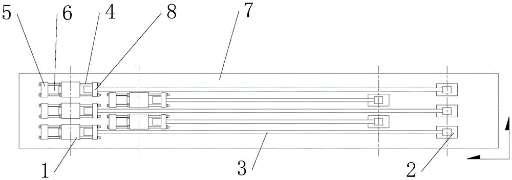
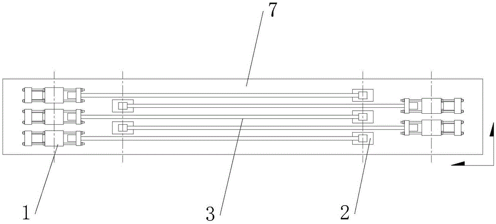
The invention discloses a concrete bridge reinforcing method and structure. The concrete bridge reinforcing method includes the following steps that firstly, at least two first anchoring seats (1) are fixed to one end of a pulled region of a concrete bridge body in a transversely-staggered manner through anchoring bolts along a concrete bridge (7) and second anchoring seats (2) are fixed to the other end of the pulled region in a transversely-staggered manner through anchoring bolts along the concrete bridge, wherein the number of the second anchoring seats is the same as that of the first anchoring seats; secondly, the two ends of each pre-stressed reinforcement (3) are installed on the corresponding first anchoring seat and the corresponding second anchoring seat, each first anchoring seat and the corresponding second anchoring seat are provided with one pre-stressed reinforcement, and the pre-stressed reinforcements are parallel; and thirdly, the pre-stressed reinforcements are tensioned to form the reinforcing structure. By the adoption of the reinforcing method, local stress concentration of the concrete bridge can be avoided, the size is small, the dead weight is low, the anti-cracking reinforcing effect can be guaranteed, and the bending resisting and reinforcing efficiency is high.

Description

technical field [0001] The invention relates to the field of strengthening bridges with an external prestressing method, in particular to a concrete bridge strengthening method and a strengthening structure. Background technique [0002] External prestressing method is a commonly used method in the field of bridge reinforcement. This method applies external force (generally eccentric setting) to the original beam structure by adding reinforcement materials and reinforcement structures. The effect of external prestressing effect is opposite to that of external load effect. , so that the beam body can store a certain amount of precompression stress to partially offset the structural self-weight effect or live load effect, thereby significantly improving the crack resistance and bearing capacity of concrete bridges, especially prestressed concrete bridges. [0003] In the field of engineering, the commonly used external prestressed reinforcement material is the prestressed stee...

Claims


Application Information

Patent Timeline
Patent Type & Authority Applications(China)
IPC IPC(8): E01D22/00E01D101/28
CPCE01D22/00E01D2101/28
Inventor 薛继连贾晋中孟宪洪葛凯牛斌马林赵体波苏永华唐永康何占元尹成斐赵德宽罗慧刚
Owner CHINA SHENHUA ENERGY CO LTD
Learn More