
Magnetron sputtering device and magnetron sputtering method

A magnetron sputtering device and magnetron sputtering technology, applied in the direction of sputtering coating, ion implantation plating, metal material coating process, etc., can solve the problem of high environmental cost of thin film preparation, difficult control of thin film uniformity, thin film The repeatability of the production process is difficult to control, etc., to achieve the effect of shortening the preparation cycle, complete functions, and good automatic control

Active Publication Date: 2016-05-04
48TH RES INST OF CHINA ELECTRONICS TECH GROUP CORP
View PDF3 Cites 24 Cited by
  • Summary
  • Abstract
  • Description
  • Claims
  • Application Information

AI Technical Summary

Problems solved by technology

With the rapid development of the flat panel display industry, optical memory industry and solar cell industry, people put forward requirements for large-area coating technology, mainly facing three problems: 1) The uniformity of the film (including film thickness, film composition, etc.) is difficult control
2) The repeatability of the film production process is difficult to control
3) The multi-layer thin film process technology faces many difficulties, including multi-cavity vacuum technology, substrate transfer technology, ultra-clean film preparation environment and high cost

Method used


Image

  • Magnetron sputtering device and magnetron sputtering method
  • Magnetron sputtering device and magnetron sputtering method
  • Magnetron sputtering device and magnetron sputtering method

Examples


Embodiment 1

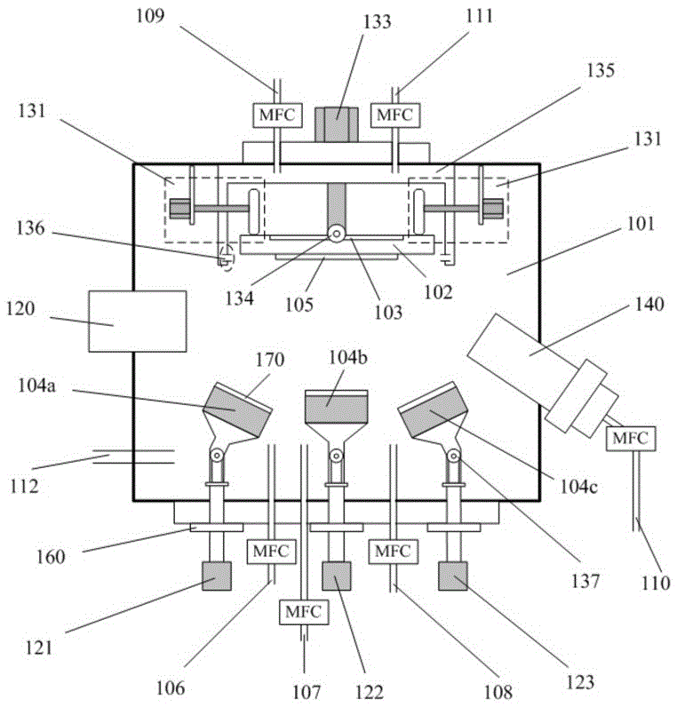
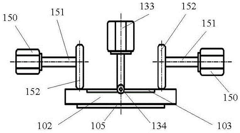
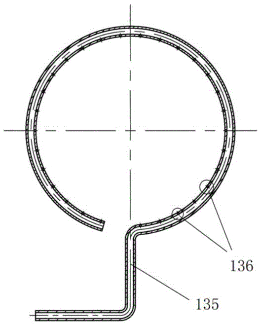
[0050] refer to Figure 1 to Figure 4 , the magnetron sputtering device of the present invention comprises:

[0051] A substrate stage 102 for placing a substrate 105;

[0052] The target 104 arranged opposite to the substrate table 102 is used to place the target material for sputtering to the substrate 105;

[0053] The reaction chamber 101, the substrate stage 102 and the target 104 are all arranged in the reaction chamber 101;

[0054] Also includes:

[0055] The angle adjusting device connected with the target 104 is used for adjusting the angle of the target 104 relative to the substrate stage 102 .

[0056] In the prior art, it is often designed that the target and the substrate table are set up facing each other, and the sputtering particles fly vertically to the substrate. When forming a film on a large-scale substrate, the film formed in the middle area of ​​the substrate is thicker, and the film formed in the edge area is thinner. In the present invention, an a...


PUM


Abstract

The invention discloses a magnetron sputtering device and a magnetron sputtering method. The magnetron sputtering device comprises a substrate table for placing a substrate, a target opposite to the substrate table and used for sputtering the substrate, and a reaction cavity for accommodating the substrate table and the target. The magnetron sputtering device further comprises an angle adjusting device corresponding to the target and used for adjusting an angle of the corresponding target to the substrate table. The magnetron sputtering method comprises the following steps: (1) the reaction cavity and the substrate are cleaned; and the target is mounted; (2) the angle of the target corresponding to the substrate and the distance between the target and the substrate are adjusted; (3) the reaction cavity is vacuumized; (4) the presputtering is performed; and meanwhile, the rotating and swinging functions of the substrate table are started; and (5) the magnetron sputtering is performed. The device can be applied to deposition of large-area films with high uniformity and excellent repeatability, and can realize continuous magnetron sputtering of multiple layers of films; and the method can save the film plating time and improve the film plating efficiency.

Description

technical field [0001] The invention belongs to the field of magnetron sputtering technology (Magnetron Sputtering), and in particular relates to a magnetron sputtering device and a magnetron sputtering method. Background technique [0002] At present, the magnetron sputtering coating technology has been developed relatively mature, and has the advantages of fast deposition speed, low substrate temperature rise, and many types of sputtering targets. The deposited film has high purity, small damage, good compactness, and uniformity. Excellent, strong adhesion, good process repeatability and other series of advantages. In addition, magnetron sputtering technology is favored by thin film manufacturers because of its relatively simple device, precise control of film thickness, and easy industrialization. With the rapid development of the flat panel display industry, optical memory industry and solar cell industry, people put forward requirements for large-area coating technolog...

Claims


Application Information

Patent Timeline
IPC IPC(8): C23C14/35
CPCC23C14/0036C23C14/35
Inventor 陈长平佘鹏程胡凡陈庆广毛朝斌张赛
Owner 48TH RES INST OF CHINA ELECTRONICS TECH GROUP CORP
Learn More