Liquid-collecting-tube assembling machine

A technology for assembly machines and liquid collection pipes, which is applied in the direction of assembly machines, metal processing, metal processing equipment, etc., can solve the problems of wasting time and manpower, wasting labor and time, and cumbersome methods and processes, so as to save manpower and time and improve Machining accuracy and the effect of improving production efficiency

Active Publication Date: 2016-05-04
SUZHOU VEDETTE IND EQUIP CO LTD
View PDF4 Cites 9 Cited by
  • Summary
  • Abstract
  • Description
  • Claims
  • Application Information

AI Technical Summary

Problems solved by technology

[0002] Liquid collection pipes are widely used in air conditioners, refrigerators and other refrigeration equipment. During the production of liquid collection pipes, it is necessary to add spacers in the middle of the pipe fittings, and plug plugs at one or both ends of the pipe fittings. In order to facilitate the installation and fixation of the spacers , both ends of the spacer are provided with protrusions. The existing processing method is to manually insert the spacer into the spacer groove of the pipe fitting, press the spacer into the spacer groove by manual or punching machine, and then manually insert the spacer on the spacer into the spacer groove. Protrusion knocking and pipe fitting riveting; then manually install the plug to the end of the pipe fitting, the manual processing method wastes labor and time, and the processing of the product is related to the operation of the worker, which may easily cause product inconsistency
The process of punching and manual processing is cumbersome, wastes time and manpower, and is not conducive to automated production

Method used


Image

  • Liquid-collecting-tube assembling machine
  • Liquid-collecting-tube assembling machine
  • Liquid-collecting-tube assembling machine

Examples


Embodiment Construction

[0024] The present invention will be further described below in conjunction with the accompanying drawings and specific embodiments.

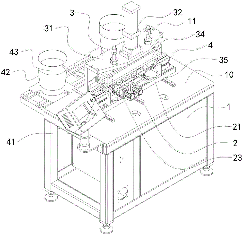
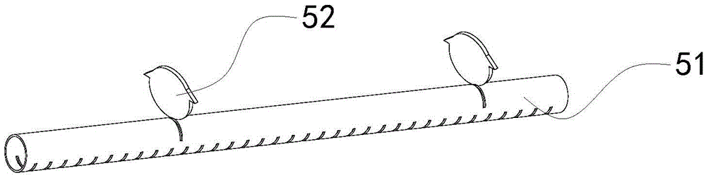
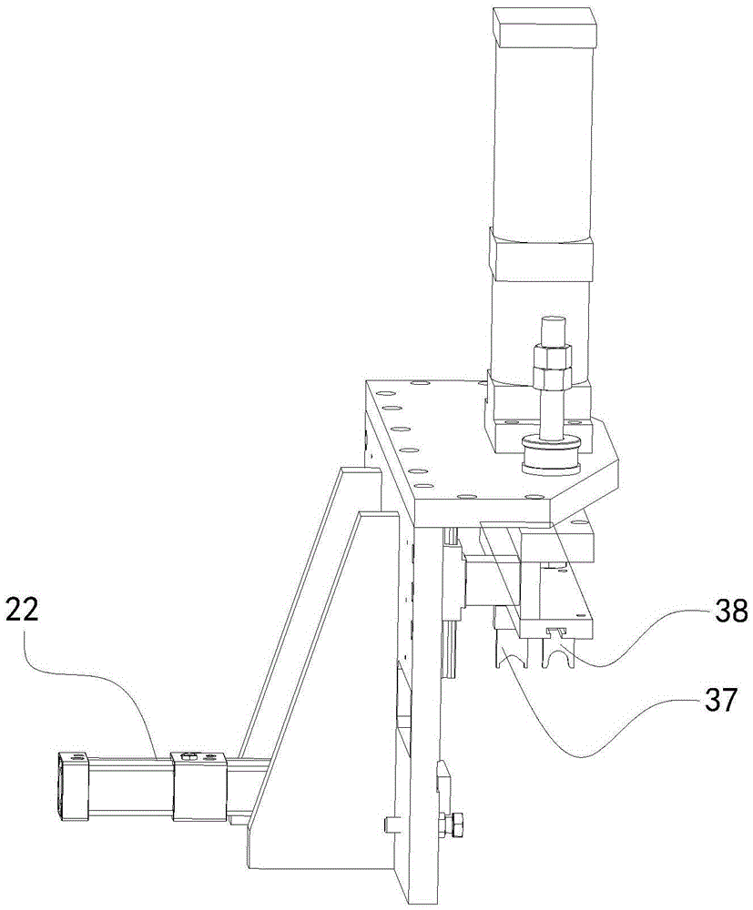
[0025] like Figure 1 to Figure 4 As shown, the collecting pipe assembly machine includes a frame 1, a workbench 10 is arranged on the frame 1, and a pipe rack device 2 for placing pipe fittings to be processed and a device for pressing down the spacer 52 are arranged on the workbench 10. Press-down device 3, press-down device 3 comprises mount 31, is provided with press-down mechanism 32 and drives press-down mechanism 32 and presses down cylinder 33 that presses down on mount 31, and press-down mechanism 32 comprises that links to each other with press-down cylinder 33 The connection plate 34 and the die structure 35 arranged on the connection plate 34; the two sides of the pipe support device 2 are respectively provided with plug installation devices 4; the pipe support device 2 is used to place the pipe fittings to be processed, and the pip...


PUM


Abstract

The invention discloses a liquid-collecting-tube assembling machine. The liquid-collecting-tube assembling machine comprises a machine frame. A workbench is arranged on the machine frame, and a tube fame device for containing a to-be-processed tube and a pressing device for pressing the product are arranged on the workbench; the pressing device comprises an installing base, and a pressing mechanism and a pressing air cylinder for driving the pressing mechanism to press are arranged on the installing base; the pressing mechanism comprises a connecting plate connected with the pressing air cylinder and a pressing mold structure arranged on the connecting plate. Plug installing devices are arranged on the two sides of the tube fame device respectively; the tube frame device is used for containing the to-be-processed tube, partition slice grooves are formed in the tube, to-be-pressed partition slices are arranged in the partition slice grooves, and protrusions are arranged at the two ends of the partition slices; the pressing mold structure is used for pressing the partition slices till the partition slices are completely installed in the partition slice grooves, and then the protrusions at the two ends of the partition slices are pressed to be riveted with the tube. The plug installing devices are arranged on the two sides of the tube frame device respectively and used for installing plugs at one end or the two ends of the tube.

Description

technical field [0001] The invention relates to the field of automation equipment, in particular to a liquid collecting pipe assembly machine. Background technique [0002] Liquid collection pipes are widely used in air conditioners, refrigerators and other refrigeration equipment. During the production of liquid collection pipes, it is necessary to add spacers in the middle of the pipe fittings, and plug plugs at one or both ends of the pipe fittings. In order to facilitate the installation and fixation of the spacers , both ends of the spacer are provided with protrusions. The existing processing method is to manually insert the spacer into the spacer groove of the pipe fitting, press the spacer into the spacer groove by manual or punching machine, and then manually insert the spacer on the spacer into the spacer groove. The protruding knockout is riveted with the pipe fittings; and then the plug is manually installed on the end of the pipe fittings. The manual processing ...

Claims


Application Information

Patent Timeline
Patent Type & Authority Applications(China)
IPC IPC(8): B23P21/00B23P19/027
CPCB23P19/001B23P19/027B23P21/002
Inventor 王强魏炳峰
Owner SUZHOU VEDETTE IND EQUIP CO LTD
Why Eureka
Try Eureka