
Plate slab flame spray gun cutting height control system and using method thereof

A flame spray gun and flame cutting technology, applied in the field of large slab flame spray gun cutting height control system, can solve the problems of affecting the slab cutting effect, high labor intensity, unable to adjust the flame spray gun cutting height, etc.

Active Publication Date: 2016-05-04
HBIS COMPANY LIMITED HANDAN BRANCH COMPANY
View PDF11 Cites 6 Cited by
  • Summary
  • Abstract
  • Description
  • Claims
  • Application Information

AI Technical Summary

Problems solved by technology

But this method has the following disadvantages: (1), the cutting height of the flame spray gun obtained by manual adjustment can only roughly achieve the purpose of heating the slab metal with the outer flame of the gas flame, but cannot be accurately realized; (2) ), affected by external factors such as the supply pressure and purity of gas fuel, the length of the outer flame of the gas flame will often change during the production process, and the traditional manual adjustment method cannot adjust the cutting of the flame spray gun in time according to the change of the outer flame length of the flame height, thus affecting the actual cutting effect of the slab; (3), in the traditional way, the on-site staff needs to adjust the cutting height of the flame spray gun according to the flame cutting effect of the previous pouring before each pouring production, Therefore, the labor intensity is high

Method used


Image

  • Plate slab flame spray gun cutting height control system and using method thereof
  • Plate slab flame spray gun cutting height control system and using method thereof
  • Plate slab flame spray gun cutting height control system and using method thereof

Examples


Embodiment Construction

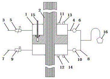
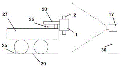
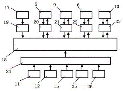
[0055] Figure 1 ~ Figure 3 It shows that the large slab flame spray gun cutting height control system of the present invention includes a cutting machine track 29, a flame cutting machine 27, a flame cutting trolley 28 arranged on the flame cutting machine 27, a pneumatic cylinder 1 installed on the flame cutting trolley 28, Piston type flame spray gun 2, camera 17 and process control system for photographing spray gun 2 and spray gun flame; Chamber air intake pipe 3 communicates with upper chamber air outlet pipe 4, and upper chamber air intake pipe 3 and upper chamber air outlet pipe 4 are respectively equipped with upper chamber electromagnetic regulating valve 5 and upper chamber electromagnetic switch valve 6; lower chamber is connected with lower chamber air inlet pipe 7 and The lower chamber outlet pipe 8 is connected, the lower chamber air intake pipe 7 and the lower chamber outlet pipe 8 are respectively installed with a lower chamber electromagnetic regulating valve...


PUM


Abstract

The invention relates to a plate slab flame spray gun cutting height control system which comprises a cutting machine rail, a flame cutting machine, a flame cutting trolley, a spray gun, a pneumatic cylinder, a camera and a process control system, wherein the flame cutting trolley is arranged on the flame cutting machine; the pneumatic cylinder is mounted on the flame cutting trolley; and the camera is used for shooting the spray gun and spray gun flame. The system using method comprises the following steps: acquiring a distance from a nozzle of the flame spray gun to a point with the highest flame temperature in real time by utilizing the camera; comparing the acquired distance with a vertical distance from the nozzle of the flame spray gun to a midpoint position of a casting blank in a thickness direction; and according to a comparison result, by a computer, controlling the piston type flame spray gun to move up and down to carry out regulation so as to guarantee that the distance between the nozzle of the flame spray gun and the point with the highest flame temperature is equal to the vertical distance between the nozzle of the flame spray gun and the midpoint position of the casting blank in the thickness direction in real time and to guarantee that a high-temperature part of the outer flame of the flame spray gun is sufficiently utilized to heat a slab, thereby fulfilling the aims of promoting plate slab cutting quality and stabilizing the continuous casting production rhythm, and greatly reducing labor intensity of field personnel.

Description

technical field [0001] The invention provides a large slab flame spray gun cutting height control system and an application method thereof, which belong to the technical field of continuous casting production control. Background technique [0002] At present, the flame cutting method is the only economical and effective way to cut large slabs with a thickness of more than 60mm in the continuous casting production process. The key to effective implementation of flame cutting technology is to ensure that the metal near the slit of the billet can be heated quickly to the ignition point of steel, which is closely related to the temperature distribution of the gas flame. The flame is divided into three parts: the outer flame, the inner flame, and the flame core. Affected by whether the fuel can be fully oxidized, the temperature of the outer flame > the temperature of the inner flame > the temperature of the flame core. Therefore, in the process of flame cutting If the hig...

Claims


Application Information

Patent Timeline
IPC IPC(8): B23K7/00B23K7/10
CPCB23K7/002B23K7/102
Inventor 贾国生成旭东范佳郭辉孙玉虎周文涛李建文王峰星
Owner HBIS COMPANY LIMITED HANDAN BRANCH COMPANY
Learn More