
Rotor assembly, pump rotor assembly, assembling method of pump rotor assembly and compressor

A component and rotor technology, which is applied in the field of compressors, rotor components, pump body rotor components and their assembly methods, can solve the problems that the balance block is easy to form disturbances and unfavorably form a stable and continuous flow field, so as to achieve the effect of improving oil return, Effects of noise reduction and fluid noise avoidance

Active Publication Date: 2016-04-27
GREE ELECTRIC APPLIANCES INC
View PDF9 Cites 4 Cited by
  • Summary
  • Abstract
  • Description
  • Claims
  • Application Information

AI Technical Summary

Problems solved by technology

[0005] Embodiments of the present invention provide a rotor assembly, a pump body rotor assembly and its assembly method, and a compressor to solve the problem that in the prior art, the balance block is easily disturbed between the oil baffle plate and the rotor, which is not conducive to forming a stable and continuous flow. field problem

Method used


Image

  • Rotor assembly, pump rotor assembly, assembling method of pump rotor assembly and compressor
  • Rotor assembly, pump rotor assembly, assembling method of pump rotor assembly and compressor
  • Rotor assembly, pump rotor assembly, assembling method of pump rotor assembly and compressor

Examples


Embodiment Construction

[0026] The present invention will be described in further detail below in conjunction with the accompanying drawings and specific embodiments, but not as a limitation of the present invention.

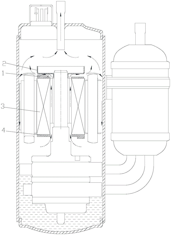
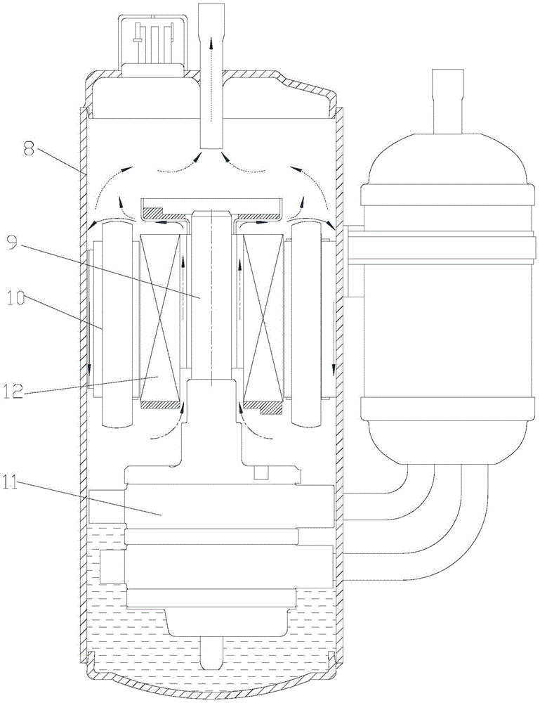
[0027] The solid line arrows in the figure indicate the flow direction of refrigeration oil, the dotted line arrows indicate the flow direction of refrigerant gas, and the dotted line arrows indicate the flow direction of oil-gas mixture.

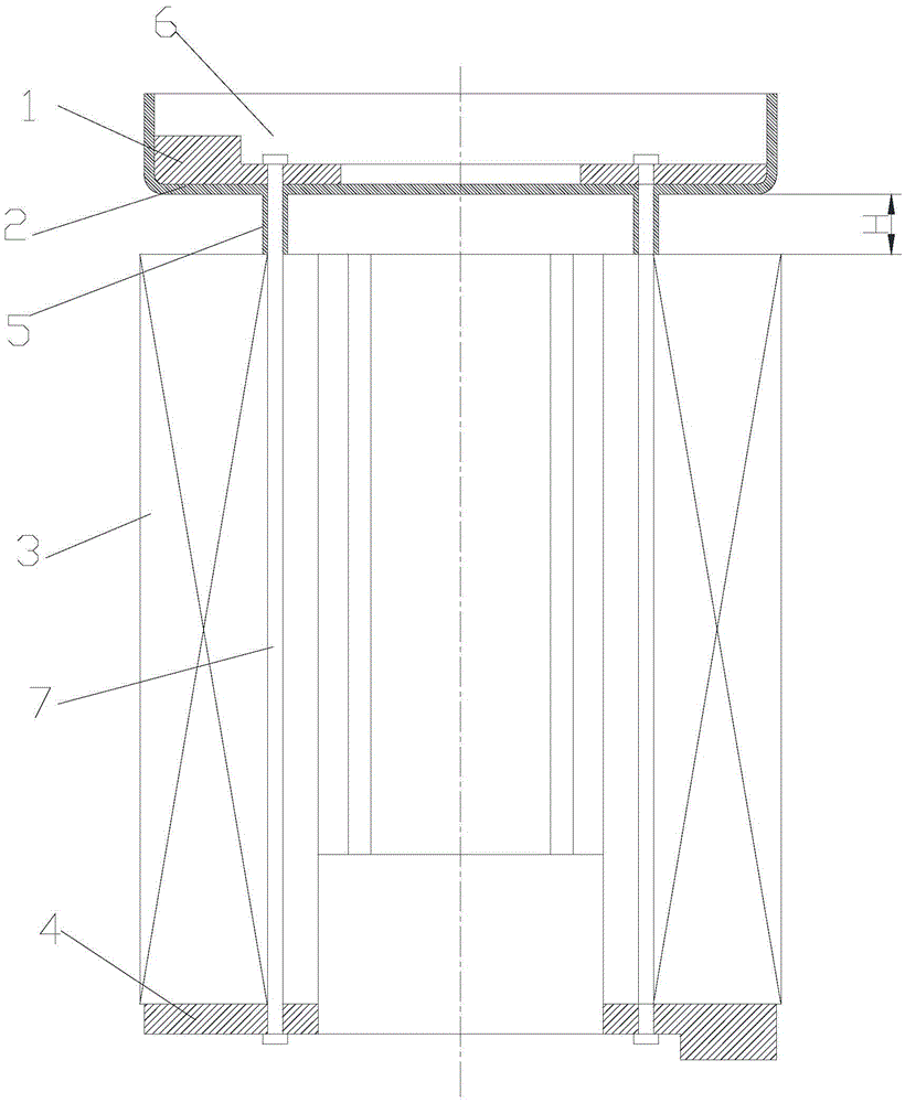
[0028] Please refer to figure 2 with image 3 As shown, the present invention provides a rotor assembly for being sleeved outside the crankshaft 9, including a first balance weight 1, an oil baffle plate 2, a rotor core 3 and a second balance weight 4, the first balance weight 1, The oil baffle plate 2, the rotor core 3 and the second balance weight 4 are sequentially arranged from top to bottom along the axial direction of the crankshaft.

[0029] Place the first balance weight 1 above the oil baffle plate 2, the space between the upper end surf...


PUM


Abstract

The invention discloses a rotor assembly, a pump rotor assembly, an assembling method of the pump rotor assembly and a compressor. The rotor assembly sleeves a crankshaft and comprises a first balancing block (1), an oil baffle plate (2), rotor iron cores (3) and a second balancing block (4), wherein the first balancing block (1), the oil baffle plate (2), the rotor iron cores (3) and the second balancing block (4) are axially arranged along the crankshaft from top to bottom in a sequence. With the adoption of the rotor assembly, the problem that the balancing blocks in the prior art easily cause disturbance between the oil baffle plate and a rotor and a stable and continuous flowing field cannot be formed well can be solved.

Description

technical field [0001] The invention relates to the technical field of air compression, in particular to a rotor assembly, a pump body rotor assembly, an assembly method thereof, and a compressor. Background technique [0002] The oil discharge of the compressor has an important impact on its own reliability and the heat transfer efficiency of the refrigeration system. With the development of miniaturization and high speed of compressors, how to design an efficient, compact and easy-to-install oil retaining structure has become an important issue in compressor design. [0003] In order to reduce the oil circulation rate of the refrigeration compressor, a current solution is to arrange the oil baffle above the balance weight on the rotor. Such as figure 1 As shown, the compressor is composed of a casing, a liquid separator, a pump body assembly, a motor stator assembly, a motor compressor, and refrigeration oil; wherein, the rotor assembly is composed of a rotor core 3 and ...

Claims


Application Information

Patent Timeline
Patent Type & Authority Applications(China)
IPC IPC(8): F04C23/02F04C29/02
CPCF04C23/02F04C29/026
Inventor 胡余生魏会军余冰杨欧翔王珺苗朋柯王明华
Owner GREE ELECTRIC APPLIANCES INC
Learn More