
Cross rolling shaft assembly and cradle head using same

A technology of rolling axis and components, which is applied in the field of gimbals, can solve the problems of cumbersome assembly, large number of parts, and high processing precision of mating surfaces, etc., and achieve the effect of improving smooth rotation, reducing rotation resistance, and reducing assembly steps

Inactive Publication Date: 2016-04-20
SZ DJI OSMO TECH CO LTD
View PDF9 Cites 8 Cited by
  • Summary
  • Abstract
  • Description
  • Claims
  • Application Information

AI Technical Summary

Problems solved by technology

[0003] 1. There are many parts and cumbersome assembly, which is not conducive to cost control;
[0004] 2. Multiple parts cooperate with each other, and the machining accuracy of the mating surface is required to be high;
[0005] 3. Mass production is not conducive to ensuring the coaxiality of the left and right arm bearing holes after final assembly

Method used


Image

  • Cross rolling shaft assembly and cradle head using same
  • Cross rolling shaft assembly and cradle head using same
  • Cross rolling shaft assembly and cradle head using same

Examples


Embodiment Construction

[0048] The following will clearly and completely describe the technical solutions in the embodiments of the present invention with reference to the accompanying drawings in the embodiments of the present invention. Obviously, the described embodiments are only some, not all, embodiments of the present invention. Based on the embodiments of the present invention, all other embodiments obtained by persons of ordinary skill in the art without making creative efforts belong to the protection scope of the present invention.

[0049] The implementation of the present invention will be described in detail below in conjunction with specific embodiments.

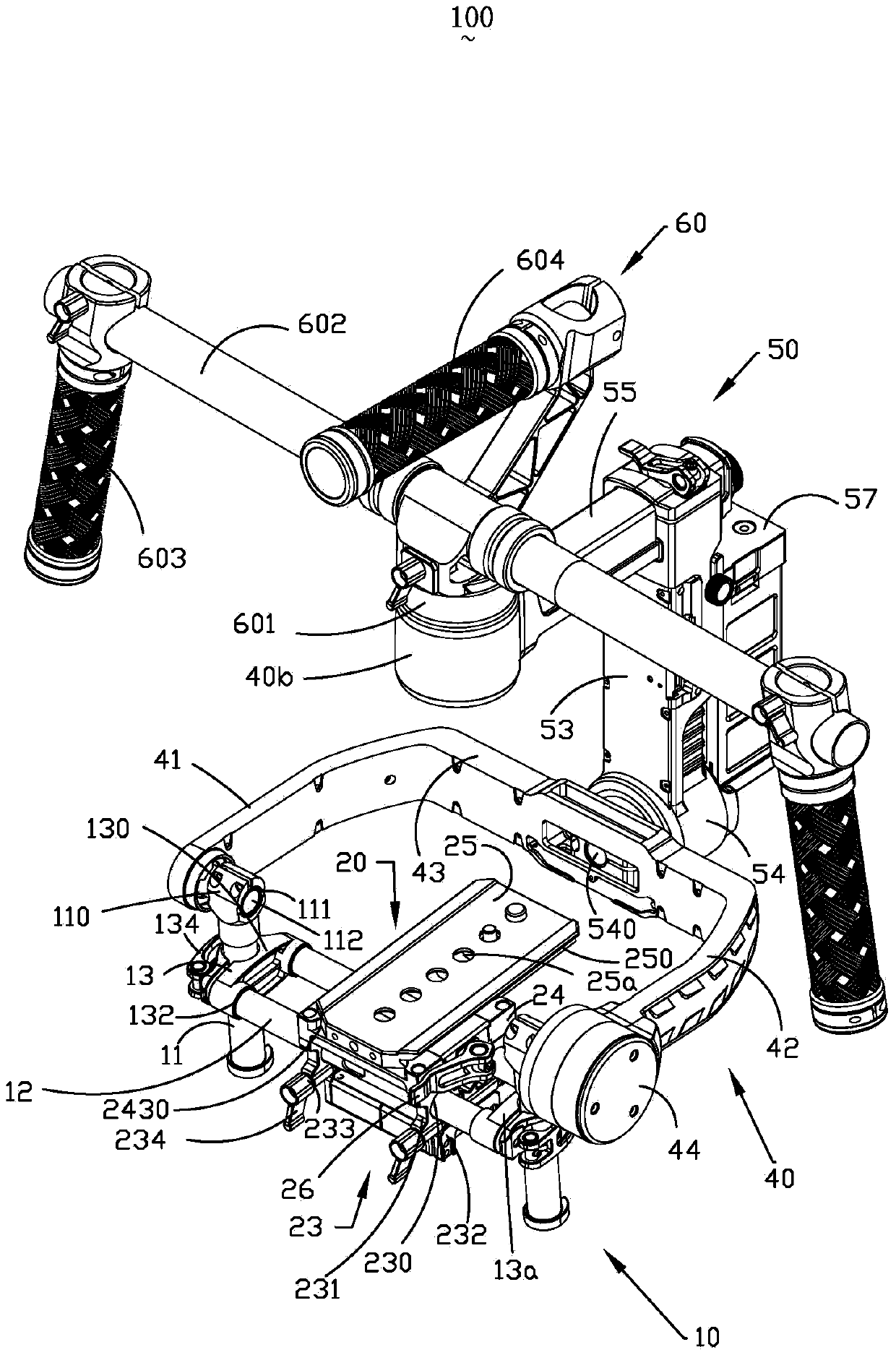
[0050] see figure 1 , a cloud platform 100 provided by the present invention is used to carry an imaging device (not shown), and the imaging device may be a camera, video camera or lens.

[0051] The cloud platform 100 includes a vertical axis assembly 10, a bracket assembly 20 movably arranged on the vertical axis assembly 10, and ...


PUM


Abstract

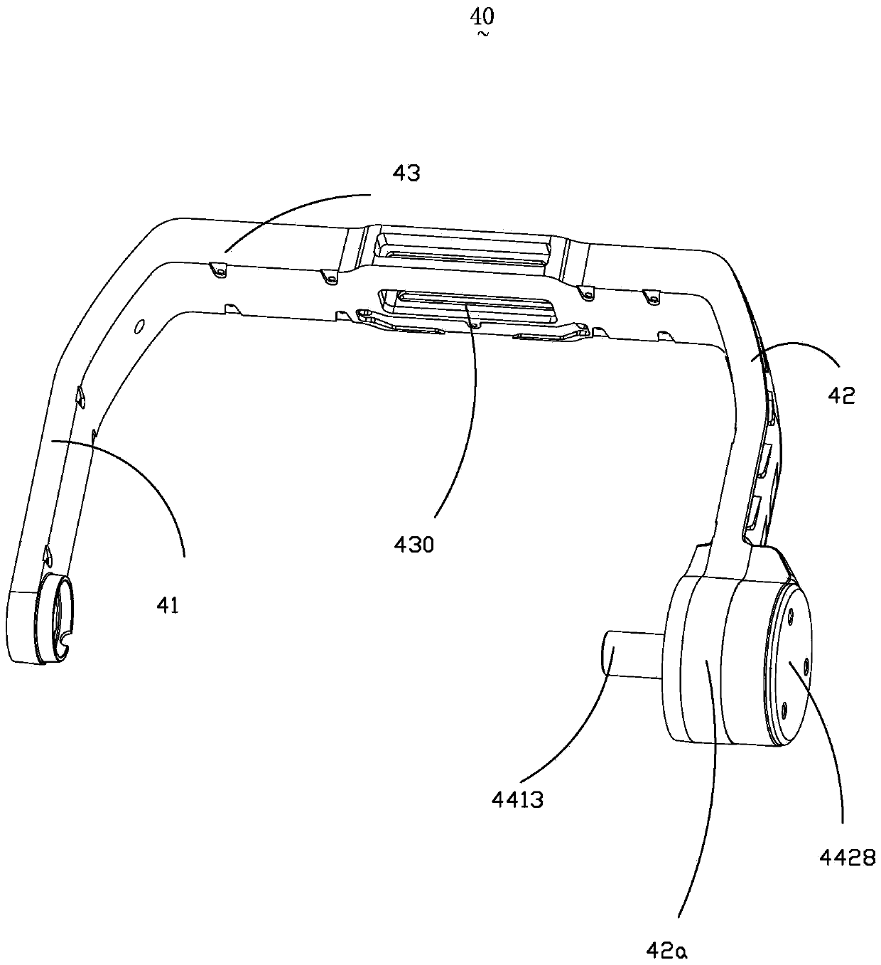
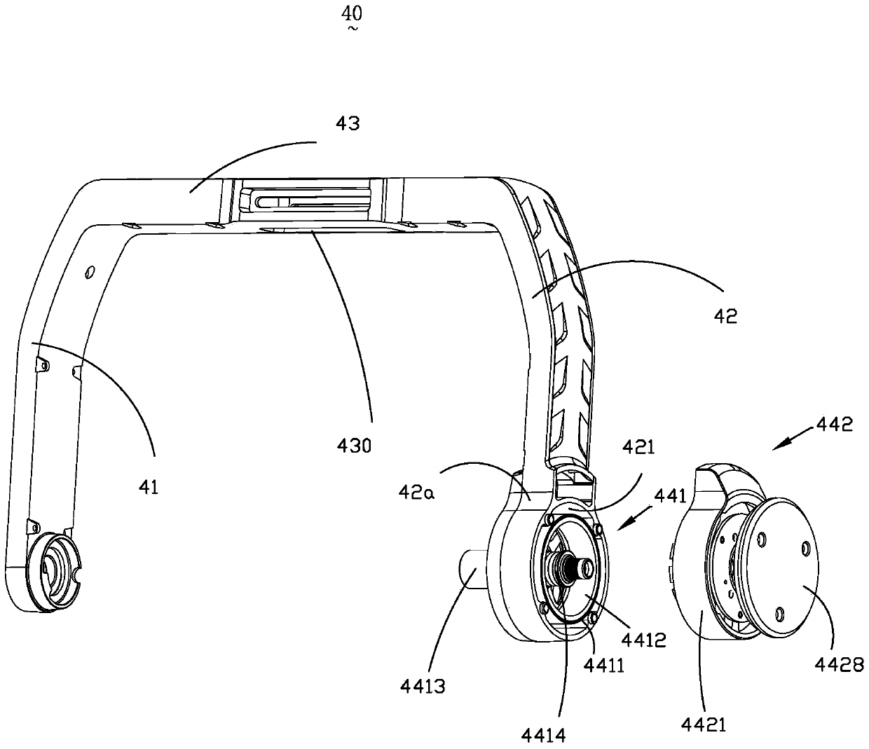
A rotating shaft assembly (40) and a cradle head (100) using the rotating shaft assembly (40). The rotating shaft assembly (40) comprises: a first supporting arm (41); a second supporting arm (42) disposed symmetrical to the first supporting arm (41); a connecting arm (43) connecting the first supporting arm (41) to the second supporting arm (42); and a first driving apparatus (44). A first bearing hole (410) is formed in the first supporting arm (41). A connecting seat (42a) is disposed at one end of the second supporting arm (42) away from the connecting arm (43). A second bearing hole (420) and an accommodating groove (421) are formed in the connecting seat (42a). The second bearing hole (420) is in communicated with the accommodating groove (421). The first driving apparatus (44) comprises a rotor assembly (441) and a stator assembly (442). The first supporting arm (41), the connecting arm (43) and the second supporting arm (42) are integrally formed. The rotor assembly (441) is directly accommodated in the accommodating groove (421).

Description

technical field [0001] The invention relates to the field of photographing equipment, in particular to a roll axis assembly and a pan-tilt used therein. Background technique [0002] The pan-tilt is a supporting workbench for installing the camera, and the camera is set on the pan-tilt. Through the adjustment of the PTZ, the lens of the camera can be adjusted to achieve correct shooting of the target. At present, the common hand-held gimbal roll axis arm and motor are designed and processed separately. The roll axis arm is usually divided into three parts: the left arm, the cross arm and the right arm. Finally, it is fixed with screws and finally assembled with the motor. . This approach has the following disadvantages: [0003] 1. There are many parts and cumbersome assembly, which is not conducive to cost control; [0004] 2. Multiple parts cooperate with each other, and the machining accuracy of the mating surface is required to be high; [0005] 3. Mass production i...

Claims


Application Information

Patent Timeline
Patent Type & Authority Applications(China)
IPC IPC(8): F16M11/12H02K7/14
CPCF16M11/045F16M11/18F16M11/2021F16M11/2071F16M11/24F16M13/04G03B17/561G03B17/563F16M11/10F16M13/00
Inventor 赵岩崇郭善光
Owner SZ DJI OSMO TECH CO LTD
Learn More