
Method, device and system for obtaining transmission path in network

A transmission path and network technology, which is applied in the field of Internet data transmission, can solve problems such as poor cluster scalability, poor fault tolerance, and inability to adapt to the network environment, and achieve the effect of reducing the amount of calculation and improving calculation efficiency

Active Publication Date: 2016-04-20
TENCENT TECH (SHENZHEN) CO LTD
View PDF9 Cites 8 Cited by
  • Summary
  • Abstract
  • Description
  • Claims
  • Application Information

AI Technical Summary

Problems solved by technology

[0005] 1. It cannot adapt to the network environment, and its fault tolerance is poor in scenarios such as network failure or jitter;
[0006] 2. Unable to provide users with the optimal path based on quality
[0009] 1. The single-machine centralized calculation path leads to poor cluster scalability. After the calculation amount reaches the single-machine bottleneck, the cluster nodes will not be able to expand capacity, and in scenarios such as network fluctuations or path failures, the path update response cycle is longer;
[0010] 2. The path selection dimension is single, and the optimal path is selected only based on the quality dimension. Without considering the path capacity, it is easy to overload the capacity of a single path, resulting in unbalanced global capacity and affecting path stability.
[0011] Aiming at the technical problem of using dynamic acceleration technology to centrally calculate the path in a single machine in the existing technology, resulting in a long period of obtaining the shortest path in the case of network fluctuations or path failures, no effective solution has been proposed yet

Method used


Image

  • Method, device and system for obtaining transmission path in network
  • Method, device and system for obtaining transmission path in network
  • Method, device and system for obtaining transmission path in network

Examples


Embodiment 1

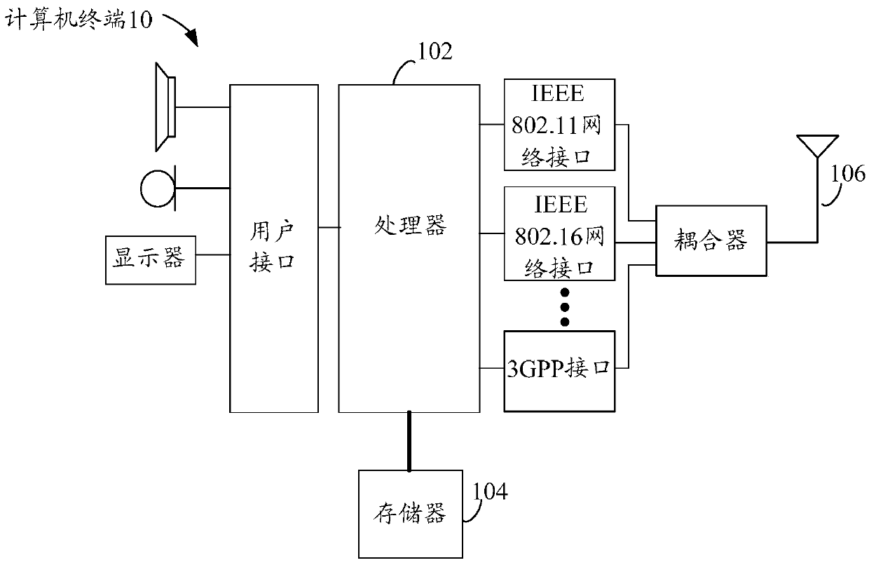
[0048] The method embodiment provided in Embodiment 1 of the present invention may be executed in a mobile terminal, a computer terminal or a similar computing device. Take running on a computer terminal as an example, figure 1 It is a structural block diagram of a computer terminal used for a method for acquiring a transmission path in a network according to Embodiment 1 of the present invention. like figure 1 As shown, the computer terminal 10 used to obtain the method for transmission paths in the network may include one or more (only one is shown in the figure) processors 102 (the processors 102 may include but not limited to microprocessors MCU or programmable logic A processing device such as a device FPGA, etc.), a memory 104 for storing data, and a transmission device 106 for a communication function. Those of ordinary skill in the art can understand that, figure 1 The shown structure is only for illustration, and it does not limit the structure of the above-mention...

Embodiment 2

[0178] According to an embodiment of the present invention, a device for obtaining a transmission path in a network for implementing the above method for obtaining a transmission path in a network is also provided, such as Figure 5 As shown, the device includes: a first acquisition module 51 , a division module 53 , a calculation module 55 and a first determination module 57 .

[0179] Wherein, the first collecting module 51 is used for collecting status data of n terminals included in the transmission network, wherein the status data at least includes: quality information of each terminal and data transmission weight between any two terminals.

[0180] In an optional solution, the quality information of each of the n terminals included in the transmission network and the data transmission weight between any two terminals may be collected through input data management.

[0181] The dividing module 53 is used for dividing n terminals into multiple terminal sets according to pr...

Embodiment 3

[0259] According to an embodiment of the present invention, a system for obtaining transmission paths in the network is also provided, such as Figure 14 As shown, the system may include: a terminal group 141 and a routing control server 143 .

[0260] The terminal group 141 includes n terminals.

[0261] The routing control server 143 is connected to the n terminals in the terminal group 141, and is used to collect the state data of the n terminals included in the transmission network, divide the n terminals into multiple terminal sets according to predetermined rules, and calculate each After the shortest path from any terminal node included in the terminal set to other terminal nodes, the shortest path between any two terminals in the transmission network is determined according to the shortest path corresponding to each terminal set. Wherein, the state data at least includes: quality data of the terminal and data transmission weight between any two terminals, and n is a n...


PUM


Abstract

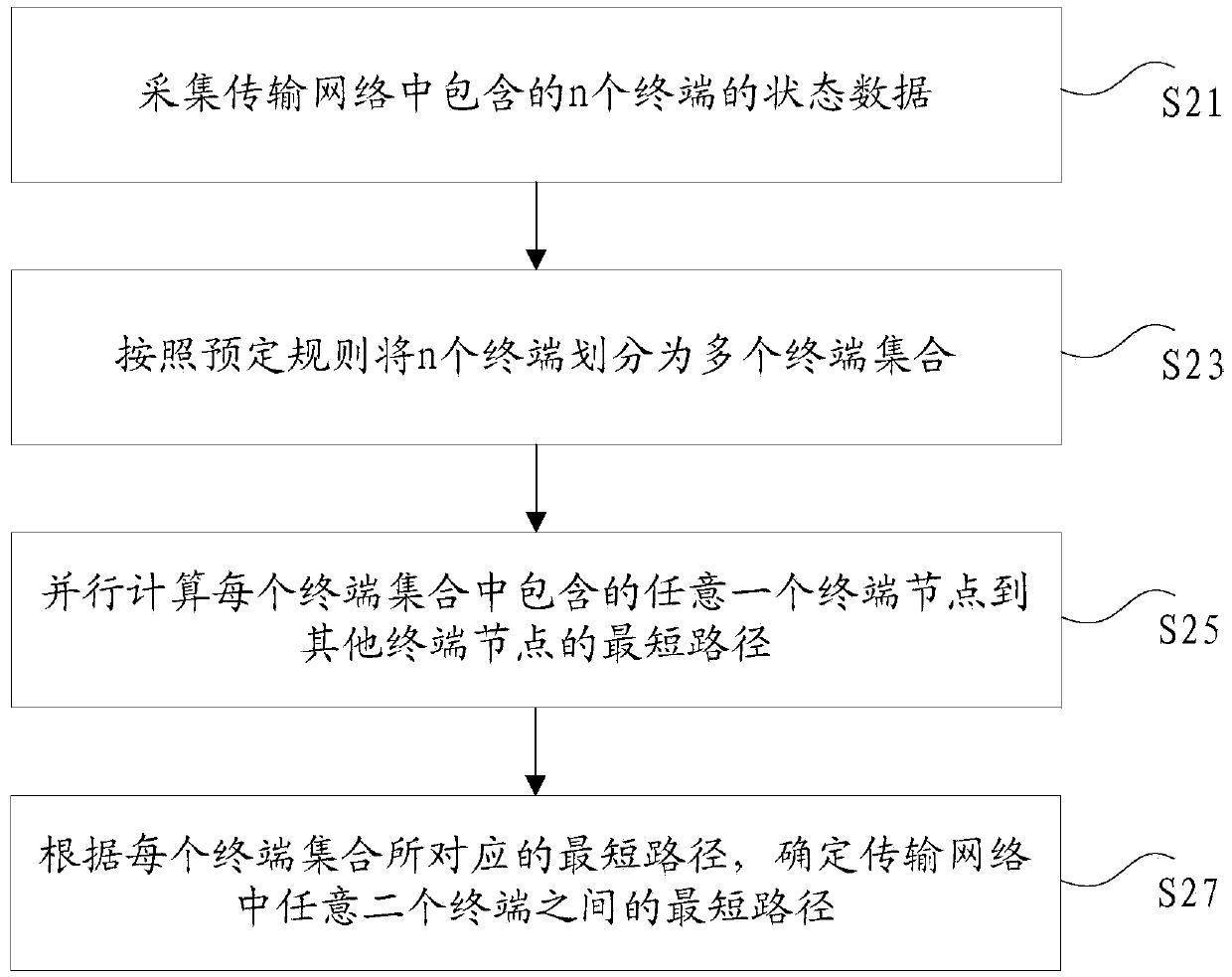
The invention discloses a method, device and system for obtaining a transmission path in a network. The method comprises: collecting state data of n terminals contained in the transmission network, wherein the state data at least comprise quality information of every terminal and data transmission weight between any two terminals; dividing the n terminals into multiple terminal sets according to a preset rule, wherein the n is a natural number; calculating the shortest paths from any one terminal node contained in every terminal set to other terminal nodes in parallel; determining the shortest path between any two terminals in the transmission network according to the shortest paths corresponding to every terminal set. According to the invention, the technical problem in the prior art that the cycle of obtaining the shortest path is long under a condition of network fluctuation or path failure when centrally calculating the paths in a single machine through a dynamic accelerating technique is solved.

Description

technical field [0001] The present invention relates to the field of Internet data transmission, in particular to a method, device and system for acquiring a transmission path in a network. Background technique [0002] In the field of Internet data transmission, a relatively common business scenario is the data transmission acceleration service, which can effectively reduce the response delay for users to access remote services. At the same time, in the domestic Internet environment, it can solve the problem of cross-operator access. Effectively improve the end-to-end connectivity. Among the existing acceleration technologies, there are mainly Tencent Interactive Entertainment TGP acceleration system and Tencent CDN acceleration system. [0003] Tencent Interactive Entertainment TGP acceleration system adopts static acceleration technology. It is an acceleration system based on pre-established nodes, statically configured fixed acceleration paths, and based on node support ...

Claims


Application Information

Patent Timeline
IPC IPC(8): H04L12/715H04L12/733H04L45/122
CPCH04L45/122H04L45/46
Inventor 朱建平朱柳嵩王红岩刘诗毅
Owner TENCENT TECH (SHENZHEN) CO LTD
Learn More