
Charge pump circuit and memory

A charge pump and circuit technology, which is used in high-efficiency power electronic conversion, conversion equipment without intermediate conversion to AC, climate sustainability, etc. question

Active Publication Date: 2016-04-20
SHANGHAI HUAHONG GRACE SEMICON MFG CORP
View PDF4 Cites 17 Cited by
  • Summary
  • Abstract
  • Description
  • Claims
  • Application Information

AI Technical Summary

Problems solved by technology

The larger the current Ibd will cause the quiescent current of the charge pump circuit 100 to be larger, so that the standby power consumption of the memory or the portable device integrated with the charge pump circuit 100 increases
[0005] Therefore, the prior art is faced with the problem that the standby current of the charge pump circuit is large and uncontrollable

Method used


Image

  • Charge pump circuit and memory
  • Charge pump circuit and memory
  • Charge pump circuit and memory

Examples

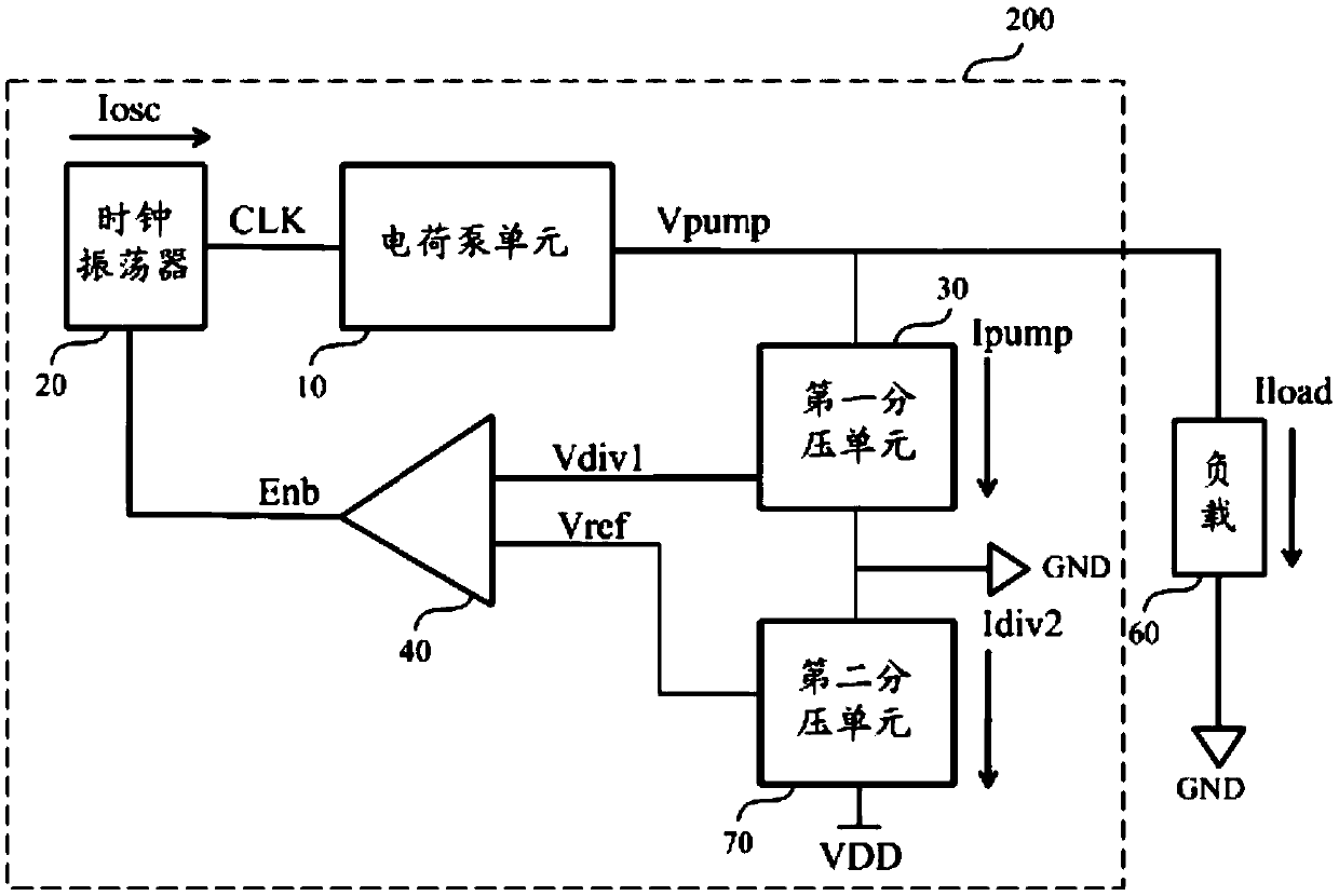
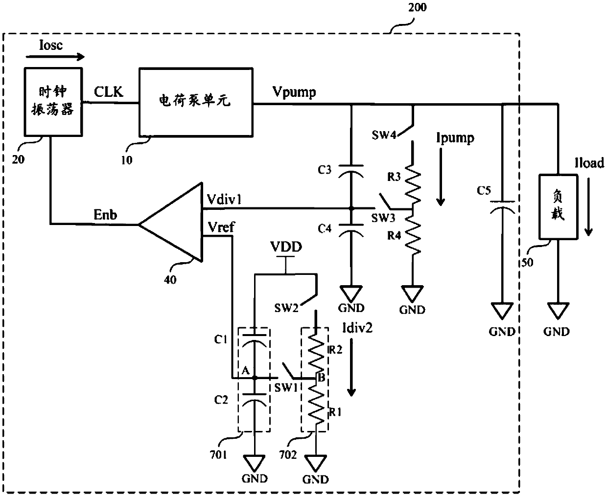

Embodiment Construction

[0025] As described in the Background Art section, since the charge pump circuit 100 (refer to figure 1 ) has a large standby current and is uncontrollable, and the standby power consumption of a memory or a portable device integrated with the charge pump circuit 100 is relatively high.

[0026] Aiming at the above-mentioned technical problems, the embodiment of the present invention discloses a charge pump circuit. By designing a voltage divider circuit, the voltage divider circuit replaces the bandgap reference source with large quiescent current in the prior art to output the reference Voltage, in the design, the current consumed by the voltage divider circuit can be controlled, thereby controlling the standby power consumption of the memory or the portable device integrated with the charge pump circuit.

[0027] In order to make the above objects, features and beneficial effects of the present invention more comprehensible, specific embodiments of the present invention wil...


PUM


Abstract

The invention provides a charge pump circuit and a memory. The charge pump circuit comprises a charge pump unit, a clock oscillator, a first partial voltage unit and a voltage comparer and further comprises a second partial voltage unit. The output end of the charge pump unit is connected with the output end of the charge pump circuit. The clock oscillator is suitable for providing a drive clock signal for the charge pump unit. The first input end of the first partial voltage unit is connected with the output end of the charge pump unit, the second input end of the first partial voltage unit is grounded, and the first partial voltage unit is suitable for outputting a first partial voltage. A reference voltage and the first partial voltage are input into the first input end and the second input end of the voltage comparer respectively, the voltage comparer is suitable for outputting a first comparison result which is used for controlling the clock oscillator to output the drive clock signal. The first input end of the second partial voltage unit is connected with a power source, the second input end of the second partial voltage unit is grounded, and the second partial voltage unit is suitable for dividing a power voltage so that the reference voltage can be output. The charge pump circuit has a low quiescent current, and the standby power consumption of the memory can be reduced.

Description

technical field [0001] The invention relates to the technical field of semiconductors, in particular to a charge pump circuit and a memory. Background technique [0002] With the development of electronic information technology, low power consumption design and application of memory products play an important role in electronic systems. A charge pump is a switched capacitor voltage converter with high conversion efficiency and simple peripheral circuits. It is widely used in modern power management circuits and is very suitable for portable applications and memories. [0003] A charge pump, also known as a switched capacitor voltage converter, can include a reference circuit, a comparison circuit, a conversion circuit, and a control circuit. The voltage boost is realized through switch arrays, oscillators, logic circuits, and comparison circuits, and capacitors are used to store energy. The charge pump can use a pulse frequency modulation scheme to generate charge only whe...

Claims


Application Information

Patent Timeline
Patent Type & Authority Applications(China)
IPC IPC(8): H02M3/07
CPCH02M3/07Y02B70/10
Inventor 黄明永肖军
Owner SHANGHAI HUAHONG GRACE SEMICON MFG CORP
Learn More