Device for measuring shearing strength index of rock-soil specimen and measuring method
A technology of shear strength and test pieces, which is applied in the direction of measuring device, using stable shear force to test material strength, strength characteristics, etc., can solve the problem of inability to measure the shear strength index of cylindrical rock and soil, and reduce the discreteness of data And other issues
- Summary
- Abstract
- Description
- Claims
- Application Information
AI Technical Summary
Problems solved by technology
Method used
Image
Examples
Embodiment 1
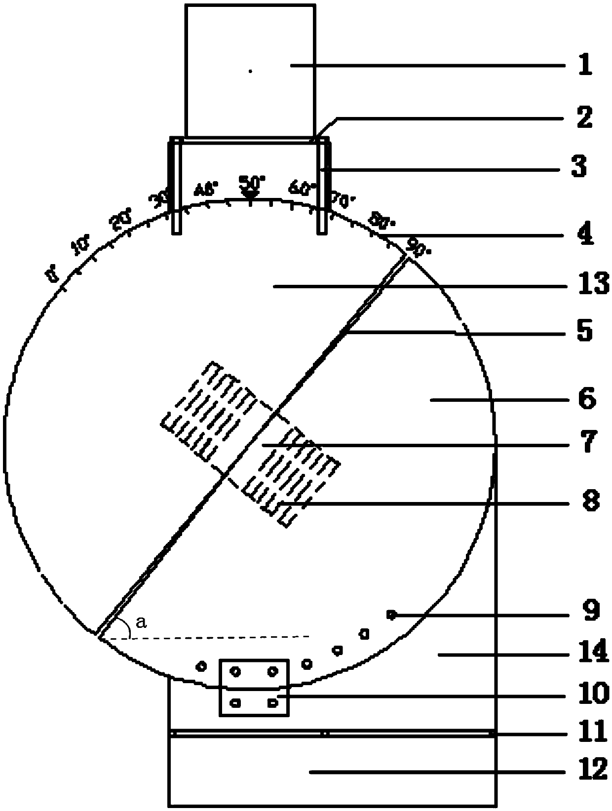
[0055] Such as Figure 1-4 All, a device for measuring the shear strength index of rock and soil specimens, which includes a horizontal base 12, and a plurality of rollers 11 are arranged on the upper horizontal plane of the horizontal base 12;
[0056] A rock-soil cylindrical specimen shear assembly is placed on a plurality of rollers 11;
[0057]In the rock-soil cylindrical specimen shearing assembly, the upper semicircular sample groove 13 engraved with the angle scale 4 is fixedly installed under the pressure bearing surface 2 through the fastening bolt 3, and the pressure bearing surface 2 is provided with an angle scale corresponding to the angle scale. Cooperating indicating arrows, the lower semicircular sample groove 6 and the upper semicircular sample groove 13 are spliced and combined to form a cylinder, and the lower semicircular sample groove 6 and the upper semicircular sample groove 13 are respectively provided with Sample loading area, the two sample loading...
Embodiment 2
[0063] The installation and working process of the above-mentioned device are as follows:
[0064] First press the pressure-bearing surface 2 and the upper semicircular sample groove 13 according to the pre-designed angle (when the upper semicircular sample groove 13 and the lower semicircular sample groove 6 are spliced together, the tooth joint 5 and the bottom of the horizontal base The angle a formed by the sides, 50°≤a≤70°, adjusted according to the angle indicated by the indicating arrow), connected together by fastening bolts 3, and then according to the designed angle of the upper semicircular sample groove 13, the lower The semicircular sample groove 6 and the shear box 14 are rotated to a corresponding angle so as to match the upper semicircular sample groove 13;
[0065] Then the lower semicircular sample groove 6 and the shear box 14 are connected and fixed together by the thin plate 10 with bolts and the mounting hole 9;
[0066] Reload;
[0067] Cover the upp...
Embodiment 3
[0070] A method for measuring the shear strength index of rock and soil specimens by using the above-mentioned device, the method comprises the following steps:
[0071] 1) take off the upper semicircle sample tank 13 of above-mentioned device and weigh, obtain its quality as M kilograms;
[0072] 2) select the cylindrical geotechnical specimen to be tested, and grind the two ends of the geotechnical specimen;
[0073] 3) The first sample loading: put the cylindrical rock and soil specimen into the lower semicircular sample groove 6 of the above device, and then fix the upper semicircular sample groove 13 and the lower semicircular sample groove 6 , rotate, so that when the lower semicircular sample groove 6 and the upper semicircular sample groove 13 are spliced together, the angle a formed by the teeth joint 5 and the bottom edge of the horizontal base 12 1 , 50°≤a 1 After ≤70°, the lower semicircular sample groove 6 is fixedly connected with the shear box 14, such as ...
PUM
| Property | Measurement | Unit |
|---|---|---|
| Height | aaaaa | aaaaa |
Abstract
Description
Claims
Application Information
 - R&D
- Intellectual Property
- Life Sciences
- Materials
- Tech Scout
- Unparalleled Data Quality
- Higher Quality Content
- 60% Fewer Hallucinations
Browse by: Latest US Patents, China's latest patents, Technical Efficacy Thesaurus, Application Domain, Technology Topic, Popular Technical Reports.
© 2025 PatSnap. All rights reserved.Legal|Privacy policy|Modern Slavery Act Transparency Statement|Sitemap|About US| Contact US: help@patsnap.com


