
Sealing device for rolling mill CVC shifting roller coupling mechanism

A technology of coupling mechanism and sealing device, which is applied in the direction of metal rolling mill stand, engine seal, metal rolling stand, etc., can solve the problems of increased grease consumption and economic cost, damaged skeleton seal, poor lubrication, etc., and saves spare parts Cost and maintenance time, extended service life, improved sealing effect

Active Publication Date: 2016-04-20
HANGANG GRP HANBAO IRON & STEEL
View PDF4 Cites 3 Cited by
  • Summary
  • Abstract
  • Description
  • Claims
  • Application Information

AI Technical Summary

Problems solved by technology

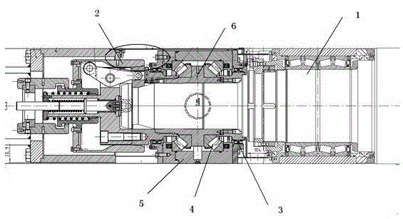
During the rolling process of the cold rolling mill, under the action of comprehensive forces such as roll bending force and roll deformation, it is inevitable to generate a huge axial component force on the roll, and the four-row tapered roller bearing is used on the intermediate roll. It can withstand large radial force but not excessive axial force, so the axial component force mainly depends on the thrust self-aligning roller bearing in the coupling and locking mechanism of the CVC intermediate roller during the rolling process; figure 1 It is a schematic diagram of the existing CVC roller shifting coupling mechanism. Since the thrust self-aligning roller bearing has a self-aligning angle of 0~2°, there is an eccentric angle of 0~2° between the coupling inner sleeve and the bearing seat, and is calculated by similar triangles The maximum swing distance of the coupling inner sleeve is 11.63mm, so the axial swing of 11.63mm during the rolling process will cause the lower half of the skeleton seal to be squeezed and damaged while the upper half has a gap; at the same time, the thrust spherical roller bearing and There is a gap of 1mm between the bearing seats, which is equivalent to the maximum offset of the theoretical centerline of the intermediate roller and the coupling inner sleeve by 2mm, which will further damage the skeleton seal; the thrust spherical roller bearing is lubricated with thin oil, and the lubrication system itself has a certain pressure. Skeleton seal damage leads to lubricating oil leakage, increasing grease consumption and economic costs; the rolling mill needs emulsion to cool and lubricate the rolls during the rolling process. Due to the skeleton seal damage and the existence of gaps, part of the emulsion will enter the CVC coupling mechanism and pollute the grease. Cause poor lubrication, shorten the life of the thrust spherical roller bearing by more than 6 months or even lock the bearing

Method used


Image

  • Sealing device for rolling mill CVC shifting roller coupling mechanism
  • Sealing device for rolling mill CVC shifting roller coupling mechanism
  • Sealing device for rolling mill CVC shifting roller coupling mechanism

Examples


Embodiment Construction

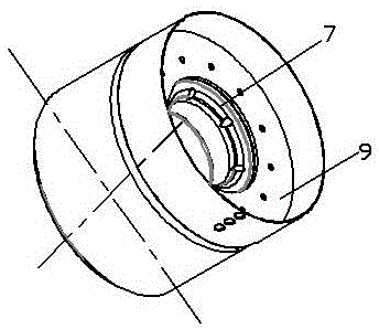
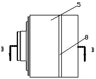
[0032] Figure 2 to Figure 5 It is shown that the present invention includes a bearing housing 5, a thrust spherical roller bearing 4 installed inside the bearing housing 5, a coupling inner sleeve 6, a roller side inner sleeve 7 set on the right side of the coupling inner sleeve 6, a transparent cover 8, and a gland 9. The sealing sleeve 10, the left compensation sealing sleeve 11 and the right compensation sealing sleeve 12, and the thrust self-aligning roller shaft, 4 are set on the outer circumference of the coupling inner sleeve 6.

[0033] Figure 5 , Figure 10 and Figure 11 It is shown that the inner sleeve 7 on the roller side is connected by two sleeves with different outer diameters, the sleeve with a smaller outer diameter is inserted into the coupling inner sleeve 6, and the inner circumference of the joint of the two sleeves is fixed with the inner sleeve on the roller side. 7 coaxial rings, 6 axial screw holes are equidistantly provided on the ring, which ar...


PUM


Abstract

The invention provides a sealing device for a rolling mill CVC shifting roller coupling mechanism. The sealing device comprises a bearing seat, a coupling inner sleeve, a thrust self-aligning roller bearing sleeving the coupling inner sleeve, a roller side inner sleeve sleeving the coupling inner sleeve, a through cover, a gland, a sealing sleeve, a left compensation sealing sleeve and a right compensation sealing sleeve; the left compensation sealing sleeve and the right compensation sealing sleeve are respectively sealed with the through cover and the gland and can achieve radial and axial movement within a certain range in the inner chamber of the through cover; a spring circumferentially mounted in a through cover circular ring is propped against the outer circumferential surfaces of the left compensation sealing sleeve and the right compensation sealing sleeve to generate a pretightening force, so that the contact surface between the left compensation sealing sleeve and the sealing sleeve and the contact surface between the right compensation sealing sleeve and the sealing sleeve form mechanical sealing surfaces. According to the sealing device for the rolling mill CVC shifting roller coupling mechanism, the originally designed framework sealing is changed to be surface-surface mechanical sealing and a sealing surface formed by an O-ring; by dynamically compensating deviation of an eccentric angle, the sealing effect can be improved, and the leakage of lubricating oil is reduced; furthermore, emulsion is prevented from entering a lubrication system, the service lives of the thrust self-aligning roller bearing and the sealing sleeve are prolonged, and the costs of spare parts and the maintenance time are reduced.

Description

technical field [0001] The invention relates to a sealing device for a CVC roll shifting coupling mechanism of a rolling mill, belonging to the technical field of strip rolling equipment. Background technique [0002] In cold-rolled strip rolling, the cold-rolling mill generally adopts six-roll CVC continuous crown to realize the control of the plate shape. During the rolling process of the cold rolling mill, under the action of comprehensive forces such as roll bending force and roll deformation, it is inevitable to generate a huge axial component force on the roll, and the four-row tapered roller bearing is used on the intermediate roll. It can withstand large radial force but not excessive axial force, so the axial component force mainly depends on the thrust self-aligning roller bearing in the coupling and locking mechanism of the CVC intermediate roller during the rolling process; figure 1 It is a schematic diagram of the existing CVC roller shifting coupling mechanism...

Claims


Application Information

Patent Timeline
Patent Type & Authority Applications(China)
IPC IPC(8): F16C33/76F16J15/34B21B31/07
CPCB21B31/078F16C33/761F16J15/3452
Inventor 刘振杰石凯秦疆曹永杰张少纬张宇王寇雄
Owner HANGANG GRP HANBAO IRON & STEEL
Learn More