Separator Vacuum Milling Cutter

A technology of splitting machine and milling cutter, which is applied in the direction of milling machine equipment, milling machine equipment details, metal processing machinery parts, etc., can solve the problems of lower production efficiency, high space occupation rate, and no anti-static mechanism, etc., to reduce production costs , prevent splashing around, better effect of dustproof

Active Publication Date: 2017-12-08
珠海市申科谱工业科技有限公司
View PDF7 Cites 2 Cited by
  • Summary
  • Abstract
  • Description
  • Claims
  • Application Information

AI Technical Summary

Problems solved by technology

When splitting the board, the milling cutter is used to separate the positions with nodes on the PCB. However, when the milling cutter mills the nodes on the PCB, it will bring out dust, and the dust will fall on the PCB. To prevent dust from remaining The PCB board is damaged on the PCB board. The operator also needs to clean the PCB board after the board is split by the board splitter. The inside of the hole is connected to the pin device. When the dust enters the groove and hole, it is difficult to remove. The dust will block the metal contact surface inside, resulting in poor contact.
[0003] At present, the existing board separators with vacuum function are all equipped with vacuum suction cups symmetrically on both sides of the milling cutter. This design has a high space occupation rate, and the production cost is also high. There is a large gap. When working for a long time or cutting at high speed, it is difficult to ensure the dust collection effect of the equipment. At the same time, there is no anti-static mechanism in the existing equipment, which increases the defect rate of the product and increases the production cost. reduced productivity

Method used


Image

  • Separator Vacuum Milling Cutter
  • Separator Vacuum Milling Cutter

Examples


Embodiment Construction

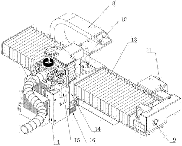
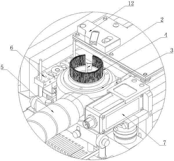
[0015] Such as figure 1 and figure 2 As shown, the present invention includes a lateral moving device, a lifting device arranged on the lateral moving device, and a milling cutter device arranged on the lifting device, and the lifting device is connected with the lateral moving device, the milling cutter device Slidingly matched with the lifting device, the milling cutter device includes a milling cutter seat 1 and a milling cutter 2 arranged on the top of the milling cutter seat 1, and a dust suction chamber 3 is also arranged on the milling cutter seat 1, so The dust-absorbing chamber 3 is covered on the periphery of the milling cutter 1, and several anti-static brushes 4 are arranged on the dust-absorbing chamber 3, and the anti-static fur brushes 4 are at the same height as the milling cutter 2. The dust suction cavity 3 is also in communication with the dust suction pipe 5 . Driven by the lateral moving device, the milling cutter holder 1 can be moved to the correspond...


PUM


Abstract

The invention discloses and provides a dust collection milling cutter structure of a board division machine. The dust collection milling cutter structure is simple in structure, produces the production cost, achieves comprehensive dust collection so as to lower the reject ratio, and meanwhile effectively prevents static electricity. The dust collection milling cutter structure comprises a transverse moving device, a lifting device arranged on the transverse moving device and a milling cutter device arranged on the lifting device. The lifting device is in sliding fit with the transverse moving device, and the milling cutter device is in sliding fit with the lifting device. The milling cutter device comprises a milling cutter base (1) and a milling cutter (2) arranged on the top of the milling cutter base (1). The milling cutter base (1) is further provided with a dust collection cavity (3). The periphery of the milling cutter (1) is wrapped by the dust collection cavity (3). A plurality of anti-static hairbrushes (4) are arranged on the dust collection cavity (3) and have the equal height as the milling cutter (2). The dust collection cavity (3) is communicated with a dust collection pipe (5). The dust collection milling cutter structure of the board division machine is applicable to the field of board division machines.

Description

technical field [0001] The invention relates to a device suitable for board splitting, in particular to a board splitter dust suction milling cutter used for PCB board splitting. Background technique [0002] In the process of manufacturing printed circuit boards (PCBs), generally multiple printed circuit boards, especially small printed circuit boards, are made on one board, and then each printed circuit board is cut, and the cut printed circuit board is usually Execute with a splitter. When splitting the board, the milling cutter is used to separate the positions with nodes on the PCB. However, when the milling cutter mills the nodes on the PCB, it will bring out dust, and the dust will fall on the PCB. To prevent dust from remaining The PCB board is damaged on the PCB board. The operator also needs to clean the PCB board after the board is split by the board splitter. The inside of the hole is connected to the device of the pin. When the dust enters the groove and the h...

Claims


Application Information

Patent Timeline
Patent Type & Authority Patents(China)
IPC IPC(8): B23C3/00B23C9/00B23Q1/62B23Q11/00B23Q11/08
CPCB23C3/00B23C9/005B23C2230/08B23Q1/621B23Q11/0046B23Q11/0825B23Q11/0866
Inventor 林柏松
Owner 珠海市申科谱工业科技有限公司
Why Eureka
Try Eureka