Driving assistance apparatus
一种驾驶辅助、驾驶员的技术,应用在控制装置、自动启动装置、驾驶员输入参数等方向,能够解决驾驶员不适感觉、没有获得加速等问题
- Summary
- Abstract
- Description
- Claims
- Application Information
AI Technical Summary
Problems solved by technology
Method used
Image
Examples
no. 1 approach
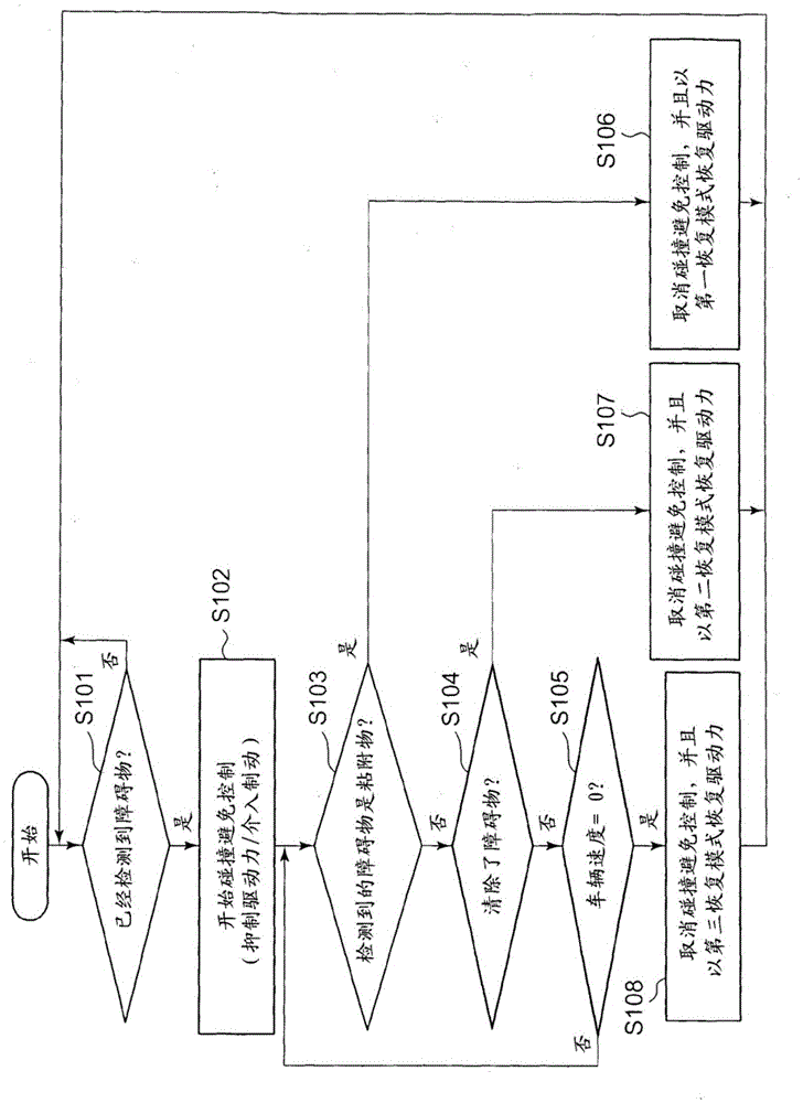
[0022] figure 1 is a block diagram showing an example of a system configuration including the driving assistance device 1 according to the present embodiment.
[0023] as in figure 1 As shown in , the driving assistance device 1 includes a driving assistance ECU 10 .
[0024] The driving assistance ECU 10 is formed of a microcomputer, and includes, for example, a ROM, a readable / rewritable RAM, a timer, a counter, an input interface, an output interface, and the like. The ROM stores control programs. The RAM stores calculation results and the like. The functions of the driving assistance ECU 10 may be realized by any one of hardware, software, and firmware, or a combination of any two or more of them. For example, selected parts or all of the functions of the driving assistance ECU 10 may be realized by an application specific integrated circuit (ASIC) or a field programmable gate array (FPGA). Part or all of the functions of the driving assistance ECU 10 may be realized ...
no. 2 approach
[0086] Next, a second embodiment will be described.
[0087] The main difference of this embodiment from the first embodiment is that the distance to the obstacle detected just now is used as an index of the possibility of the presence of an obstacle around the host vehicle. Hereinafter, the same reference numerals denote constituent elements similar to those of the first embodiment, and differences will be mainly described.
[0088] The system configuration of the driving assistance device 1 according to the present embodiment is as in the case of the first embodiment in figure 1 , so its description is omitted.
[0089] Next, a flow chart of driving assistance performed by the driving assistance device 1 according to the present embodiment, particularly a flow chart of driving assistance performed for collision avoidance, including intervention to suppress driving force and then recovering the suppressed driving force, will be described. .
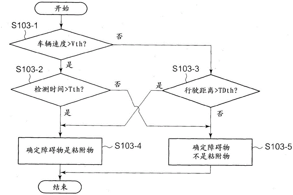
[0090] Figure 5 is a flowcha...
no. 3 approach
[0098] Next, a third embodiment will be described.
[0099] The main difference between this embodiment and the first embodiment is whether the recovery mode is selected by the driver and the recovery mode selected by the driver is used as an index of the possibility of an obstacle existing around the host vehicle. Hereinafter, the same reference numerals denote constituent elements similar to those of the first embodiment, and differences will be mainly described.
[0100] The system configuration of the driving assistance device 1 according to the present embodiment is as in the case of the first embodiment in figure 1 , so its description is omitted.
[0101] Next, a flow chart of driving assistance performed by the driving assistance device 1 according to the present embodiment, particularly a flow chart of driving assistance performed for collision avoidance, including intervention to suppress driving force and then recovering the suppressed driving force, will be descri...
PUM
 Abstract
Description
Claims
Application Information
 - R&D
- Intellectual Property
- Life Sciences
- Materials
- Tech Scout
- Unparalleled Data Quality
- Higher Quality Content
- 60% Fewer Hallucinations
Browse by: Latest US Patents, China's latest patents, Technical Efficacy Thesaurus, Application Domain, Technology Topic, Popular Technical Reports.
© 2025 PatSnap. All rights reserved.Legal|Privacy policy|Modern Slavery Act Transparency Statement|Sitemap|About US| Contact US: help@patsnap.com


