
Control device of hybrid vehicle

A technology for a hybrid vehicle and a control device, which is applied in the directions of a hybrid vehicle, a power device, a control device, etc., can solve the problems such as the reduction of the durability of the locking mechanism and the like

Inactive Publication Date: 2018-03-16
TOYOTA JIDOSHA KK
View PDF6 Cites 1 Cited by
  • Summary
  • Abstract
  • Description
  • Claims
  • Application Information

AI Technical Summary

Problems solved by technology

In such a hybrid vehicle, when the transmission torque that causes the rotation fluctuation of the first rotation element is input from the driving wheel side, the rotation of the first rotation element will be rendered non-rotatable due to the rotation fluctuation of the first rotation element. There is a possibility that the durability of the above-mentioned locking mechanism may be reduced due to the load applied to the locking mechanism for fixing.

Method used


Image

  • Control device of hybrid vehicle
  • Control device of hybrid vehicle
  • Control device of hybrid vehicle

Examples


Embodiment Construction

[0028] Hereinafter, embodiments of the present invention will be described in detail with reference to the drawings.

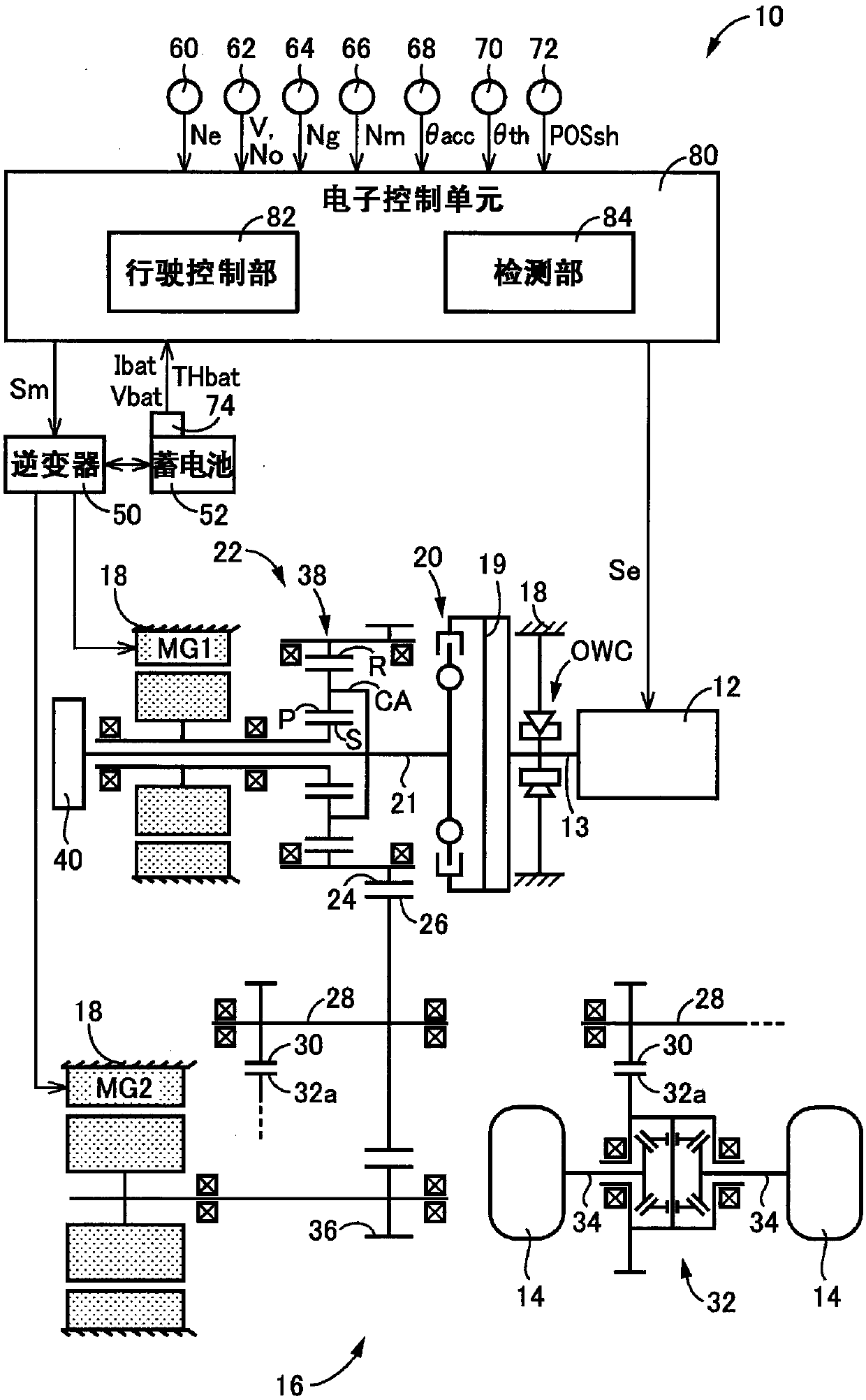
[0029] figure 1 It is a diagram explaining the schematic configuration of each part related to the travel of the vehicle 10 to which the present invention is applied, and the main parts of a control system for controlling the above-mentioned respective parts. and, figure 2 It is a partial cross-sectional view for explaining the connecting portion between the crankshaft 13 and the input shaft 21 described below.

[0030] exist figure 1 Here, the vehicle 10 is a hybrid vehicle including an engine 12 capable of serving as a driving force source for driving that generates drive torque, a first rotating machine MG1 , and a second rotating machine MG2 as a plurality of driving force sources. Further, vehicle 10 includes drive wheels 14 and a power transmission device 16 provided on a power transmission path between engine 12 and drive wheels 14 .

[0031] The e...


PUM


Abstract

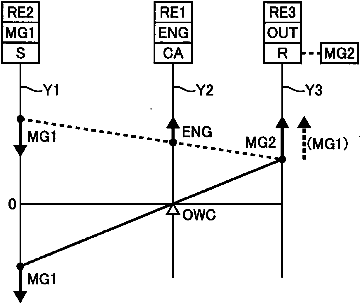
The invention provides a control device of a hybrid vehicle. When a rotational fluctuation of the output rotational members of the transmission portion (for example, ring gears R of the planetary gearmechanism) is detected while the hybrid vehicle is travelling in the EV2 mode, the MG1 torque Tg becomes zero. Therefore, the increased amount of torque Tg resulting in a rotational fluctuation of the carrier CA of the planetary gear mechanism caused by the MG1 torque Tg is cancelled, and a shock input to the one-way clutch OWC is reduced. Thus, it is possible to restrain the deterioration of durability of the lock mechanism (one-way clutch OWC) against a rotational fluctuation of the third rotational element (ring gears R). In addition, in restraining the deterioration of durability of the one-way clutch OWC, reaction force caused by the MG1 torque Tg is not input to the ring gears R of the planetary gear mechanism, and thus, it is possible to restrain a shock or unintended deteriorationof the driving force.

Description

technical field [0001] The present invention relates to a control device for a hybrid vehicle capable of driving both a first rotating machine and a second rotating machine for traveling in a state in which a predetermined rotating element in a differential mechanism is fixed in a non-rotatable manner. power source to drive. Background technique [0002] A control device for a hybrid vehicle is known at present, which includes an engine, a first rotating machine, a differential mechanism, a second rotating machine, and a lock mechanism. A first rotating element, a second rotating element connected to the first rotating machine in a power-transmittable manner, and a third rotating element connected to a drive wheel, the second rotating machine being connected to the above-mentioned rotating machine in a power-transmittable manner The drive wheel is connected, and the lock mechanism fixes the first rotating element in a non-rotatable manner. For example, a control device for...

Claims


Application Information

Patent Timeline
Patent Type & Authority Applications(China)
IPC IPC(8): B60W20/20B60W10/02B60W10/08B60W10/12B60L50/16
CPCB60W10/02B60W10/08B60W10/12B60W20/20B60W30/20B60W20/15B60K6/365B60K6/383B60K6/445B60K2006/381B60W20/10B60W2710/083B60W2552/35Y02T10/62Y02T10/72B60W2556/00Y02T10/7072B60W2710/242
Inventor 土田充孝铃木岐宣铃木阳介马场伸一加藤晃一末永真一郎
Owner TOYOTA JIDOSHA KK
Learn More