An integrated device for follow-up locking and automatic unlocking

An automatic unlocking and follow-up technology, applied in the direction of the antenna support/installation device, etc., can solve the problems of cumbersome and fragmented operation steps, extremely high matching accuracy requirements, and many positioning components, etc., to improve the efficiency of erection and retraction, and the matching accuracy. Low requirements, high working reliability and the effect of

Active Publication Date: 2019-08-02
ANHUI SUN CREATE ELECTRONICS
View PDF2 Cites 0 Cited by
  • Summary
  • Abstract
  • Description
  • Claims
  • Application Information

AI Technical Summary

Problems solved by technology

The disadvantage of using the bolt-fixed structure is that it relies too much on professional tools for disassembly and assembly, and the operation steps are cumbersome and fragmented
The defects of the locking pin structure are as follows: firstly, the matching precision between the locking pin and the key hole is extremely high, and if the precision is slightly deviated, the antenna will inevitably shake or even be inaccurately positioned.
Although the method of conical surface matching can be used to ensure the accurate insertion of the locking pin and the locking hole to a certain extent, the fundamental problem of the matching accuracy of the two is still unsolved, and the locking pin and the locking hole are stuck and the locking is not in place. Occurs from time to time, which leads to prestress between the pin shaft and the pin hole, which eventually affects the normal erection and withdrawal of the antenna
Secondly, the locking pin is not conducive to frequent repeated disassembly and insertion, which will cause serious wear and tear on the pin body, thereby exacerbating the above-mentioned inaccurate positioning of the antenna and other defects
Finally, similar to the bolt fixing method, due to the complex structure of the radar antenna, there are many parts to be positioned. Each time the locking and unlocking operations are completed, there are generally a large number of independent disassembly and assembly operations, which takes up the time for the system to be removed. Greatly reduces the maneuverability of the radar

Method used


Image

  • An integrated device for follow-up locking and automatic unlocking
  • An integrated device for follow-up locking and automatic unlocking

Examples


Embodiment Construction

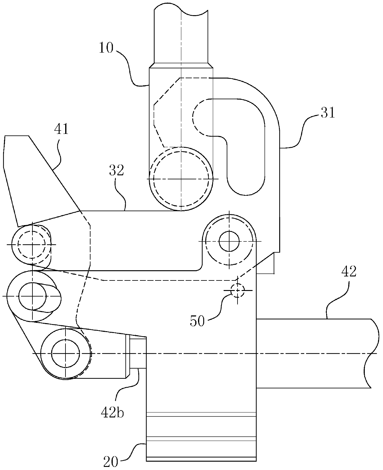
[0023] For ease of understanding, here in conjunction with accompanying drawing, specific implementation structure and work flow of the present utility model are described as follows:

[0024] Concrete structure of the present invention, as Figure 1-2 As shown, it includes a locking rod 10 fixed on the antenna to be locked by welding or other means, and a locking seat 20 for performing follow-up locking and automatically unlocking the above-mentioned locking rod 10 . The locking seat 20 is provided with the following locking components: the power part 42 formed by the combination of the one-way oil cylinder and the compression spring 42a, the seesaw 41 hinged with the piston rod 42b of the power part 42, and the positioning notch on the seesaw 41 41a is a torsion spring hinged lock hook that fits in place; the axes of the above-mentioned hinged parts are all parallel to each other. During design, the torsion spring hinged lock hook is composed of the hook body 31, the hook h...


PUM


Abstract

The invention belongs to the technical field of radar antennae, and particularly relates to a follow-up locking and automatic unlocking integrated device. The follow-up locking and automatic unlocking integrated device comprises a locking bar and a locking seat. The locking seat is provided with a torsion spring hinging lock hook and a lock hook fixing assembly. The hook body of the torsion spring hinging lock hook forms a cooperation end which is used for hooking the locking bar. The open direction of the hook body of the torsion spring hinging lock faces the locking advancing direction of the locking bar. Furthermore the advancing path of the locking bar is in skew perpendicularity with the axis of an articulated shaft of the torsion spring hinging lock hook. The elastic restoring direction of the torsion spring at the articulated shaft of the torsion spring hinging lock hook is opposite to the force applying direction of the locking bar relative to the hook body. A hook handle is formed through outward extending from the locking bar pressed side of the hook body. The lock hook fixing assembly comprises a seesaw and a power part. The seesaw is provided with a positioning recessed part which is used for hooking the hook handle. The follow-up locking and automatic unlocking integrated device can effectively ensure quick and reliable locking and unlocking action after a mechanism is mounted in position, thereby efficiently realizing conversion operations of the radar antenna in multiple states.

Description

technical field [0001] The invention belongs to the technical field of radar antennas, and in particular relates to a follow-up locking and automatic unlocking integrated device for meeting the requirements of rapid erection and withdrawal of radar antennas. Background technique [0002] Under modern high-tech conditions, high mobility is an important tactical indicator of vehicle-mounted radar, and whether the radar antenna can be reliably erected and withdrawn in the shortest time is an important means to improve the above-mentioned mobility. In order to facilitate the transition between the erection and withdrawal states of the radar antenna, bolt fixing or locking pin structures are usually used at present to achieve the purpose of fast and reliable locking of the moving radar mechanism components. Among them, the bolt-fixed structure is to use bolts to directly fasten the connection points of each structure after the antenna is turned over to a designated position. The...

Claims


Application Information

Patent Timeline
Patent Type & Authority Patents(China)
IPC IPC(8): H01Q1/12
CPCH01Q1/12
Inventor 金小飞周雷
Owner ANHUI SUN CREATE ELECTRONICS
Why Eureka
Try Eureka