
Inverse time inversion-based through-the-wall radar reference surface correction method

A technology of datum correction and through-wall radar, which is applied to radio wave measurement systems, instruments, etc., and can solve the problem of limited accuracy of target position correction

Inactive Publication Date: 2016-04-13
NANJING UNIV OF INFORMATION SCI & TECH
View PDF7 Cites 3 Cited by
  • Summary
  • Abstract
  • Description
  • Claims
  • Application Information

AI Technical Summary

Problems solved by technology

However, the algorithm still completely depends on the time delay estimation, and the accuracy of target position correction will still be limited by the accuracy of time delay estimation

Method used


Image

  • Inverse time inversion-based through-the-wall radar reference surface correction method
  • Inverse time inversion-based through-the-wall radar reference surface correction method
  • Inverse time inversion-based through-the-wall radar reference surface correction method

Examples


Embodiment Construction

[0081] The present invention will be further described below with reference to the accompanying drawings.

[0082] The present invention provides a method for calibrating a through-wall radar datum plane based on reverse time inversion, comprising the following steps:

[0083] 1) Establish a through-wall imaging model;

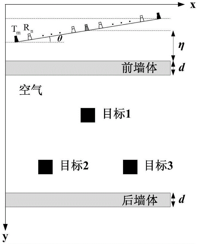
[0084] like figure 1 As shown, suppose that the target to be searched is placed between two layers of walls, and the two layers of walls are the front wall and the rear wall in turn; for example figure 1 As shown in , the target is a square electrical conductor, namely target 1, target 2 and target 3; the front wall and the rear wall are uniform dielectric plates, the thickness of the uniform dielectric plate is d, and the relative permittivity is ε r , the conductivity is σ, and the specific parameter values ​​of the uniform dielectric plate are input into the simulation system for simulation according to the model requirements;

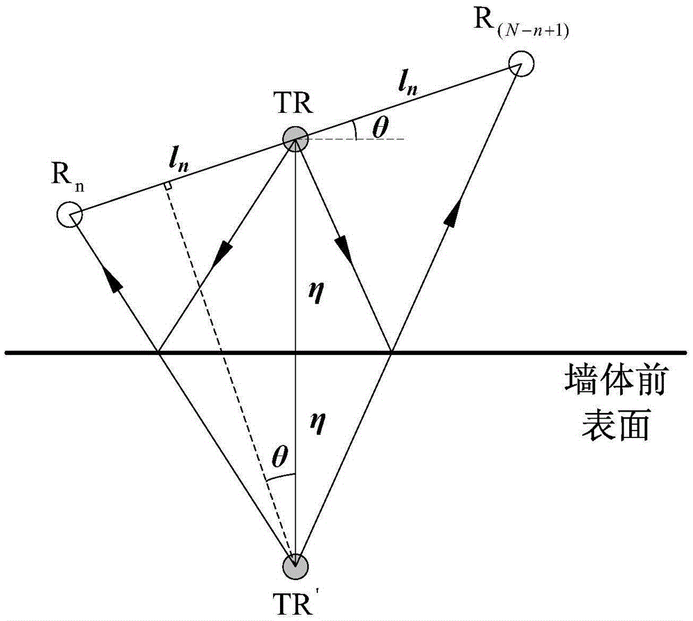
[0085] like figure 1 and...


PUM


Abstract

The invention discloses an inverse time inversion-based through-the-wall radar reference surface correction method. An oblique angle between an antenna array and a horizontal plane and a vertical distance between the array center of the antenna array and a wall body are estimated according to echo time delay; the coordinates of antenna array elements and a horizontal reference surface are determined; the oblique antenna array is expanded to the horizontal reference surface according to the inverse problem principle of electromagnetic wave propagation; and echo signals received by a virtual antenna array located at a horizontal measurement line are adopted to replace echo signals received by the antenna array located at an oblique measurement line, so that real scene imaging can be realized. According to the inverse time inversion-based through-the-wall radar reference surface correction method, a wave equation is adopted, so that the condition of electromagnetic wave propagation in space can be described more authentically; and the oblique antenna array is extended to the horizontal reference surface, and therefore, influence of target dislocation and distortion caused by the oblique antenna array can be effectively eliminated. Compared with the prior art, the inverse time inversion-based through-the-wall radar reference surface correction method has the advantages of higher imaging precision, easiness in implementation and great significance in practical application.

Description

technical field [0001] The invention relates to a method for correcting a reference plane, in particular to a method for correcting a reference plane of a through-wall radar based on reverse time inversion, and belongs to the technical field of through-wall radar imaging. Background technique [0002] Ultra-wideband through-wall imaging radar plays an indispensable role in the search and rescue of anti-terrorism and earthquake disasters. In the existing literature related to ultra-wideband through-wall radar, most of the models are built with the antenna array close to the wall or with the The walls are parallel. However, in practical applications, it is impossible to ensure that the antenna array is parallel to the wall, especially in some special occasions, such as anti-terrorism or hostage rescue. If the existing algorithms are directly applied to the tilted antenna array without any modification, the algorithms based on delay estimation will produce large errors, and so...

Claims


Application Information

Patent Timeline
IPC IPC(8): G01S7/40
CPCG01S7/40
Inventor 李家强蔡洪渊陈金立朱艳萍
Owner NANJING UNIV OF INFORMATION SCI & TECH
Learn More