
Dual-layer compound seal blocking mechanism

A double-layer composite, plugging disk technology, applied in the direction of engine sealing, fluid tightness testing, machine/structural component testing, etc. Achieve the effect of improving flexibility, large renovation space, and cost reduction

Active Publication Date: 2016-04-13
SHANGHAI AUTOMOBILE GEAR WORKS +1
View PDF9 Cites 5 Cited by
  • Summary
  • Abstract
  • Description
  • Claims
  • Application Information

AI Technical Summary

Problems solved by technology

However, when this technology is used for sealing, it is necessary to manually place the mechanism in the required sealing hole, and then move the handle to drive the cam to drive the spring to shrink through the recovery of the pull rod, and the sealing ring will expand and tighten to realize the sealing action; the sealing process needs to be divided into two parts. step, manual operation is required, and the blocking position must also be confirmed manually, which cannot be quickly and automatically located
[0004] After searching the existing technology, it is found that the Chinese patent document number CN204175956U, published (announcement) date 2015.02.25, discloses an internal expansion mechanical sealing mechanism, which uses a cylinder to directly push the sealing mechanism to place the required sealing hole Inside, fix the top of the positioning sleeve on the end face of the required plugging hole, continue to push the pull rod and then compress the spring, and the sealing ring will expand and tighten to realize the sealing action. The diameter of the hole blocked by this device is generally less than 20mm, and it cannot simultaneously Multi-layer shell position for sealing

Method used


Image

  • Dual-layer compound seal blocking mechanism
  • Dual-layer compound seal blocking mechanism
  • Dual-layer compound seal blocking mechanism

Examples


Embodiment 1

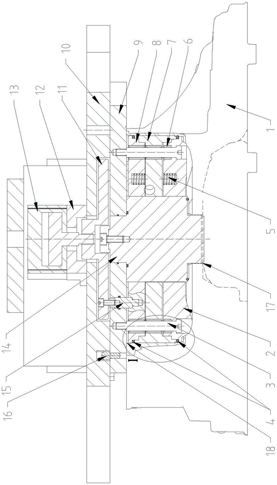
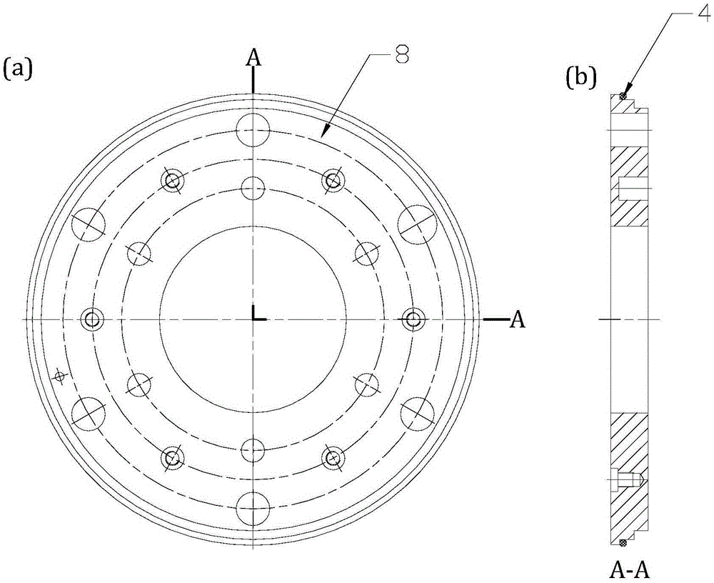
[0020] Such as figure 1 and figure 2 As shown, this embodiment includes: a clamping cylinder part, a blocking plate 9, an upper blocking disk 8, a lower blocking disk 2 and an intermediate disk 7, wherein: the clamping cylinder part is fixedly connected with the upper blocking disk 8, and the sealing The blocking plate 9 is arranged between the clamping cylinder part and the upper blocking plate 8;

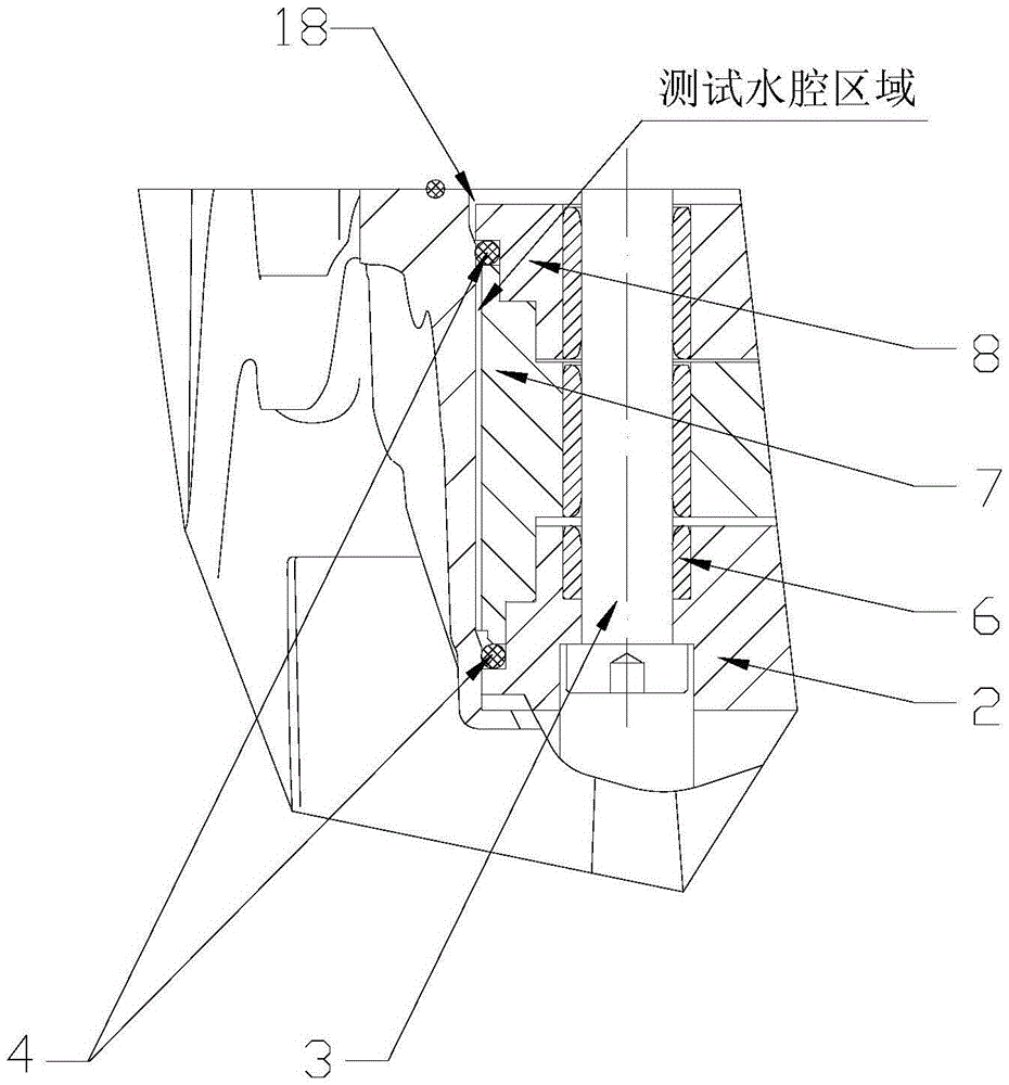
[0021] The upper blocking disk 8, the lower blocking disk 2 and the intermediate disk 7 are elastically connected by a balance spring 5, and there is a clearance fit between the intermediate disk 7 and a sealing ring 4, and the upper and lower sealing rings 4 After compression and expansion, the test water tank area is formed with the inner wall of the housing 1 .

[0022] The clamping oil cylinder part includes: an oil cylinder 13, an oil cylinder base 12 and a connection plate 11 connected in sequence, wherein: the oil cylinder 13 is arranged on the oil cylinder base 12 and i...


PUM


Abstract

The invention belongs to the technical field of gearbox housing seal tests, and relates to a dual-layer compound seal blocking mechanism. The blocking mechanism is arranged in a blocking hole and specifically comprises a clamping oil cylinder component, a blocking plate, an upper blocking disc, a lower blocking disc and a middle disc. The clamping oil cylinder component and the upper blocking disc are fixedly connected, and the blocking plate is arranged between the clamping oil cylinder component and the upper blocking disc. The upper blocking disc, the lower blocking disc and the middle disc are in interference fit and are provided with seal rings and elastically connected. During clamping, automatic sealing of the blocking hole can be achieved by means of pushing of an oil cylinder and compressing of the seal rings, automatic reset can be achieved through a balance spring during releasing, cost is reduced, and the flexibility of a machine tool is improved.

Description

technical field [0001] The invention relates to a technique in the field of transmission housing seal testing, in particular to a double-layer composite seal sealing mechanism. Background technique [0002] In the air tightness test of the gearbox casing, the holes on the casing are all sealed with end faces. For holes with a diameter of more than 300mm, or when there are openings on the inner surface of the hole, the use of end face sealing technology can no longer meet the requirements of air tightness testing. Therefore, it is necessary to design a sealing mechanism with a simple structure, so that it can not only meet the sealing requirements, but also be easy to maintain and replace the seal. [0003] After searching the prior art, it was found that Chinese patent document number CN103759006A, published (announcement) date 2014.04.30, discloses an internal expansion sealing device for camshaft holes, including a pull rod, a rear end inner sleeve, an inner sleeve, Fron...

Claims


Application Information

Patent Timeline
Patent Type & Authority Applications(China)
IPC IPC(8): F16J15/06G01M3/00
CPCF16J15/06G01M3/00
Inventor 朱金良姜宇峰郁骏飞
Owner SHANGHAI AUTOMOBILE GEAR WORKS
Learn More