
Bottom plate structure with rock foundation, of underground structure

A technology for rock foundations and underground structures, applied in underwater structures, infrastructure engineering, water conservancy projects, etc., can solve the problems of a single calculation model for subway structures and does not consider the influence of geological conditions on the structural floor, and reduce the number of floor and side panels. The effect of stress on the bottom of the wall, reducing the thickness and reducing the cost of the project

Inactive Publication Date: 2016-04-13
CHINA RAILWAY TUNNEL SURVEY & DESIGN INST
View PDF3 Cites 1 Cited by
  • Summary
  • Abstract
  • Description
  • Claims
  • Application Information

AI Technical Summary

Problems solved by technology

[0003] The calculation model of the subway structure is single, and the influence of the geological conditions under the structural floor is not considered

Method used


Image

  • Bottom plate structure with rock foundation, of underground structure
  • Bottom plate structure with rock foundation, of underground structure
  • Bottom plate structure with rock foundation, of underground structure

Examples


Embodiment 1

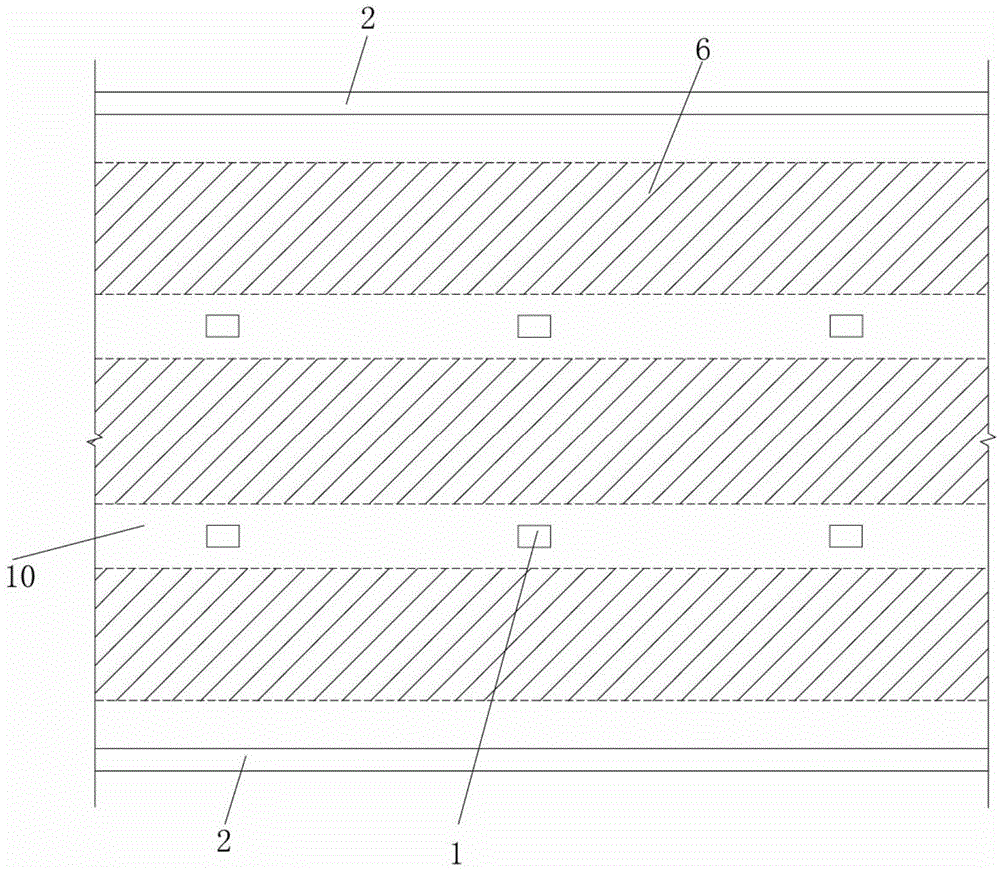
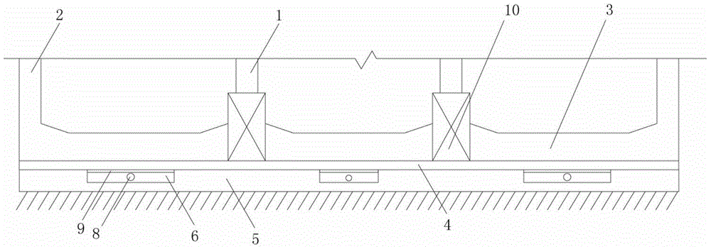
[0037] Such as Figure 1-2 As shown, the Kaifusi Station of the Changsha-Zhuzhou-Tanzhou Intercity Railway is a 3-story underground station with a thickness of about 3.5m. The station structure is a 3-span box-shaped structure with a longitudinal column spacing of 12m. The structural size according to the conventional design: the thickness of the roof is 0.80m, the thickness of the first and second basement floors is 0.4m, the thickness of the structural side wall 2 is 1m, the thickness of the bottom plate 3 is 1.2m, and the cross-section of the column 1 is 0.8m×1.2m. The geology of the site is: artificial fill, silty clay, garden gravel, strongly weathered slate, moderately weathered slate and weakly weathered slate, the structural floor 3 is located on the weakly weathered slate, and the thickness of the weakly weathered slate above floor 3 is greater than 10m , The saturated compressive strength of weakly weathered slate is 9.7-13MPa, medium weathered slate and weakly weath...

Embodiment 2

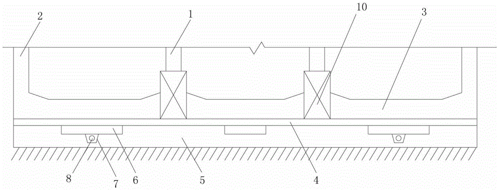
[0040] Such as figure 1 , 3As shown, the Kaifusi Station of the Changsha-Zhuzhou-Tanzhou Intercity Railway is a 3-story underground station with a thickness of about 3.5m. The station structure is a 3-span box-shaped structure with a longitudinal column spacing of 12m. The structural size according to the conventional design: the thickness of the roof is 0.80m, the thickness of the structural side wall 2 is 1m, the thickness of the bottom plate 3 is 1.2m, and the section of the column 1 is 0.8m×1.2m. The geology of the site is: artificial fill, silty clay, garden gravel, strongly weathered slate, moderately weathered slate and weakly weathered slate, the structural floor 3 is located on the weakly weathered slate, and the thickness of the weakly weathered slate above floor 3 is greater than 10m , The saturated compressive strength of weakly weathered slate is 9.7-13MPa, medium weathered slate and weakly weathered slate are almost impervious to water. Due to the safety requir...


PUM


Abstract

The invention belongs to the technical field of underground structure engineering, and particularly relates to a bottom plate structure with a rock foundation, of an underground structure. The bottom plate structure with the rock foundation is characterized by comprising columns, side walls, a bottom plate, bottom plate longitudinal beams, a concrete cushion layer, the rock foundation and soft cushion layers, wherein the side walls and the bottom plate longitudinal beams are arranged above the bottom plate; the columns are arranged on the top surfaces of the bottom plate longitudinal beams; the concrete cushion layer is arranged at the bottom of the bottom plate; the rock foundation is arranged at the bottom of the concrete cushion layer; and the soft cushion layers are arranged at the bottom of the concrete cushion layer. According to the invention, stresses on the bottom plate and the sidewalls of the underground structure, the thicknesses of the bottom plate and the sidewalls, and reinforcements of the bottom plate and the sidewalls, can be reduced, thus anti-floating pile construction can be omitted, and raw materials can be saved; and good vertical bearing capacity and water isolation performance of the rock foundation are adequately utilized, thus the stresses on the bottom plate and the bottoms of the sidewalls can be reduced, concrete and steel bars can be saved, and engineering costs can be decreased.

Description

technical field [0001] The invention belongs to the technical field of underground structure engineering, and in particular relates to a bottom plate structure of an underground structure of a rock foundation. Background technique [0002] At present, the subway structure is designed according to the box structure, taking into account the soil pressure, water pressure, ground vehicle load and structure self-weight. The calculation model of the subway structure is a symmetrical planar frame structure supported on an elastic foundation, and an earth spring is used under the frame structure floor to simulate the soil resistance. Structural calculation adopts two working conditions: full water level working condition and zero water level working condition. Taking the most common 11m-wide single-column island platform station standard section in China as an example, the thickness of the roof covering soil is 3m, and the main dimensions of the subway structure are: the thickness ...

Claims


Application Information

Patent Timeline
Patent Type & Authority Applications(China)
IPC IPC(8): E02D29/045E02D19/20
Inventor 杜道龙贺维国朱世友江水德江婕瑞杨世东朱剑平徐韬刘丽
Owner CHINA RAILWAY TUNNEL SURVEY & DESIGN INST
Learn More