Oil separation lifting treatment method for restaurant wastewater

A technology of catering wastewater and treatment methods, which is applied in multi-stage water treatment, flotation water/sewage treatment, multi-stage water/sewage treatment, etc., and can solve the problems of failure to achieve the effect of pretreatment, reluctance to clean grease, inconvenient management, etc. problems, to achieve the effect of improving decontamination and degreasing effects, reducing daily maintenance costs, and ensuring stable and reliable operation

Inactive Publication Date: 2016-04-13
ANHUI TIANJIAN ENVIRONMENTAL PROTECTION
View PDF6 Cites 4 Cited by
  • Summary
  • Abstract
  • Description
  • Claims
  • Application Information

AI Technical Summary

Problems solved by technology

[0003] 1. The oil separation effect of the traditional grease trap and grease trap is poor, and the pretreatment has not achieved the effect, which affects the subsequent sewage treatment process;
[0004] 2. The volume of the oil separation tank is too large and occupies a large area;
[0005] 3. Since the sundries in the sewage are not well separated, they enter the oil separation tank, and the long-term deposition needs to be cleaned or cleaned manually, and the operating environment is quite poor;
[0006] 4. The volume utilization rate of the oil separation box is not high;
[0007] 5. Traditional equipment requires large investment and inconvenient management;
[0008] 6. The water inlet and outlet structure of the pipeline in the equipment is prone to short flow, eddy current and circulating flow;
[0009] 7. Manual oil skimming is required, the operating environment is poor, unsafe and reliable, which brings a lot of trouble to the oil cleaning work, causing the operators to be unwilling to clean the oil, making the equipment unable to use normally, and the water output is not up to standard

Method used


Image

  • Oil separation lifting treatment method for restaurant wastewater
  • Oil separation lifting treatment method for restaurant wastewater

Examples


Embodiment Construction

[0031] The following will clearly and completely describe the technical solutions in the embodiments of the present invention with reference to the accompanying drawings in the embodiments of the present invention. Obviously, the described embodiments are only some, not all, embodiments of the present invention. Based on the embodiments of the present invention, all other embodiments obtained by persons of ordinary skill in the art without making creative efforts belong to the protection scope of the present invention.

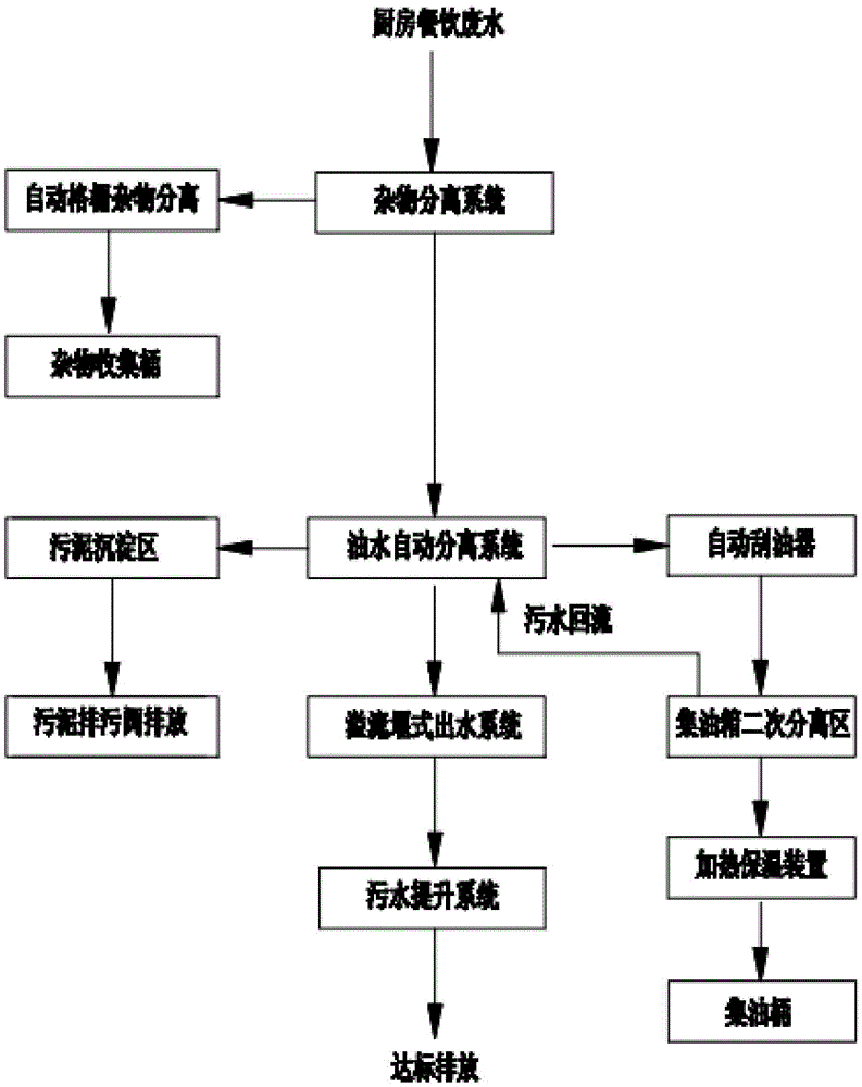
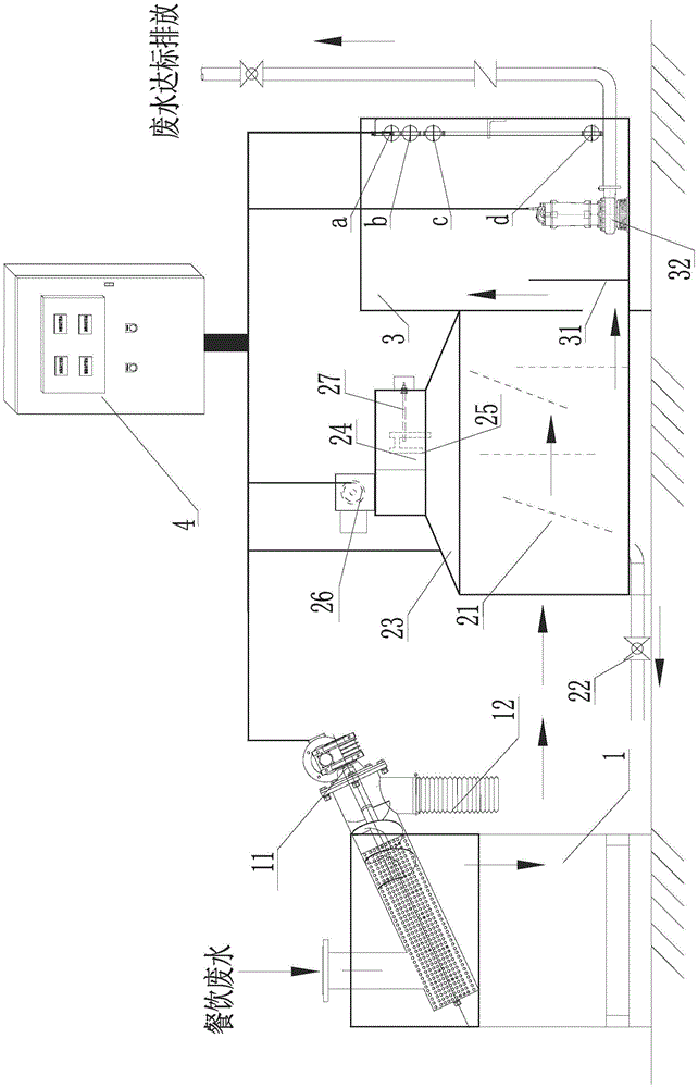
[0032] The catering wastewater oil-separating and lifting treatment method of the present invention cooperates with the catering wastewater oil-separating and lifting equipment to realize the following three major steps: step 1, separation of catering wastewater and sundries; step 2, using an oil-water separation box to realize oil-water separation; step 3, using The sewage lifting box realizes the lifting and discharge of sewage. In combination, see figure 1...


PUM


Abstract

The invention discloses an oil separation lifting treatment method for restaurant wastewater. The method includes the following steps of firstly, separating sundries out of restaurant wastewater; secondly, achieving oil-water separation through an oil-water separation tank; thirdly, achieving sewage lifting discharge through a sewage lifting box. At least one liquid distribution baffle of a porous structure is additionally arranged at the liquid inlet position of the oil-water separation tank, and the baffles stand in the oil-water separation tank in a perpendicular state or an inclined state so that a fed liquid distribution guide system can be formed. An overflow weir type water sealing device is adopted between the oil-water separation tank and the sewage lifting box. When wastewater enters the oil-water separation tank, it can be ensured that a uniform flow dividing effect and the effect of reducing short flow and turbulent flow of wastewater are achieved, so that flowing dead zones are avoided; it can also be ensured that water layer stability breakage caused when discharged water in the sewage lifting box is too concentrated and forms vortexes in water layers is avoided.

Description

technical field [0001] The invention relates to a method for treating catering wastewater, in particular to a method for treating catering wastewater through oil separation and lifting. Background technique [0002] At present, the treatment method of most catering oily wastewater is to build a new grease trap or build a grease trap. According to the test results of oil-water separation, the longer the residence time of oily wastewater from catering in the static oil separation equipment, the better the effect of separating floating oil from water. The existing traditional oil trap equipment and technologies mainly include: traditional civil construction grease traps, such as: advection type grease traps, inclined plate type grease traps, small grease traps, a non-powered grease trap, etc. This traditional oil separation method is relatively traditional technology, relatively backward, the main shortcomings are: [0003] 1. The oil separation effect of the traditional grea...

Claims


Application Information

Patent Timeline
Patent Type & Authority Applications(China)
IPC IPC(8): C02F9/02
CPCC02F1/001C02F1/24C02F1/40C02F9/00C02F2301/08
Inventor 孟行健孟维俊
Owner ANHUI TIANJIAN ENVIRONMENTAL PROTECTION
Why Eureka
Try Eureka