Parallel leg structure for legged robot capable of running at high speed
A robot and footed technology, applied in the field of parallel leg structure of footed robots, can solve problems such as large energy consumption, achieve large step length, avoid large amount of calculation and small inertia
- Summary
- Abstract
- Description
- Claims
- Application Information
AI Technical Summary
Problems solved by technology
Method used
Image
Examples
specific Embodiment approach 1
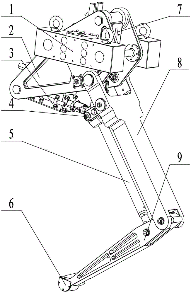
[0017] Specific implementation mode one: as Figure 1~6 As shown, the parallel leg structure for a high-speed running legged robot in this embodiment includes a shoulder blade 2, a horizontal hydraulic cylinder 3, a parallel short connecting rod 4, a parallel long connecting rod 5, a sole 6, a vertical hydraulic cylinder 7, and a thigh 8 , calf 9 and two joint legs load-bearing and lifting steel plate 1;
[0018] The scapula 2 is a frame body symmetrical on both sides, and the load-bearing and lifting steel plates 1 of the two joint legs are symmetrically fixed on the outer walls of both sides of the scapula 2 , the upper end of the thigh 8 is hinged to the lower part of the scapula 2 , and the lower end of the thigh 8 is connected to the lower part of the calf 9 . The upper end is hinged, the sole of the foot 6 is fixed on the lower end of the calf 9, the parallel short link 4 is hinged with the upper part of the thigh 8, the other end of the parallel short link 4 is hinged w...
specific Embodiment approach 2
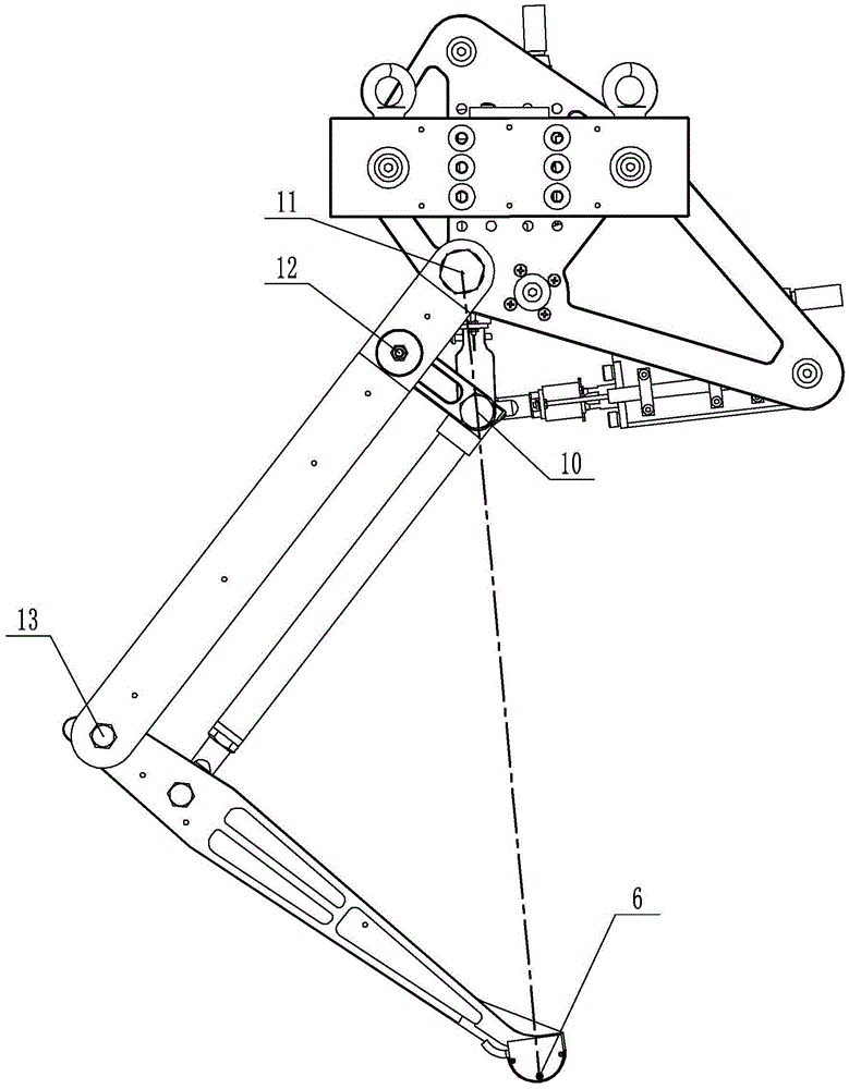
[0020] Specific implementation mode two: as figure 2 As shown, in this embodiment, the parallel short link 4 and the parallel long link 5 are connected through the first hinge point 10, the parallel short link 4 and the thigh 8 are connected through the second hinge point 12, and the thigh 8 and the calf 9 The thigh 8 and the scapula 2 are connected through the hip joint 11, the triangle formed by the first hinge point 10, the second hinge point 12 and the hip joint 11 is connected with the hip joint 11, the knee joint 13 and the sole 6 The formed triangle is a similar triangle; the parallel short connecting rod 4 is arranged parallel to the calf 9, the parallel long connecting rod 5 is arranged parallel to the thigh 8, and the three points of the hip joint 11, the first hinge point 10 and the center of the sole 6 are in a straight line superior. The structure of the above-mentioned magnifying ruler constitutes the profiling mechanism of the force, position and speed of the ...
specific Embodiment approach 3
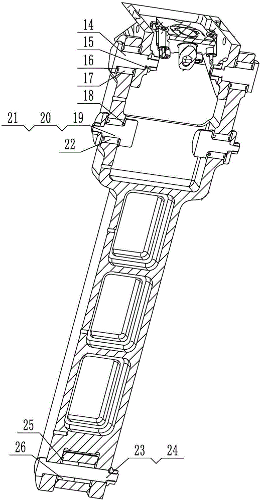
[0021] Specific implementation mode three: as image 3 As shown, the hip joint 11 of this embodiment includes a first pin shaft 14, a first hexagon flange nut 15, a first thrust self-lubricating bearing 16 and a first needle roller bearing 17, and the thigh 8 and the shoulder blade 2 pass through the pin shaft 14 is rotationally connected, the first needle roller bearing 17 is set on the first pin shaft 14, and the first pin shaft 14 is locked by the first hexagon flange nut 15 and the first thrust self-lubricating bearing 16. With such arrangement, the structure is simple and compact, the installation is convenient, and the intermediate space for the vertical hydraulic cylinder can be freed up. Other components and connections are the same as those in the second embodiment.
PUM
 Abstract
Description
Claims
Application Information
 - R&D
- Intellectual Property
- Life Sciences
- Materials
- Tech Scout
- Unparalleled Data Quality
- Higher Quality Content
- 60% Fewer Hallucinations
Browse by: Latest US Patents, China's latest patents, Technical Efficacy Thesaurus, Application Domain, Technology Topic, Popular Technical Reports.
© 2025 PatSnap. All rights reserved.Legal|Privacy policy|Modern Slavery Act Transparency Statement|Sitemap|About US| Contact US: help@patsnap.com


